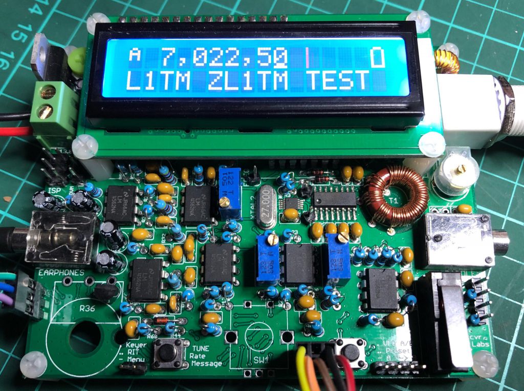
I plan to use this category of my blog as a kind of sub-site to track the building of this delightful new transceiver kit from Hans Summers G0UPL and his QRP Labs. Since its launch in late August when all stock sold out in a day, sales of the QCX CW Transceiver continue at a pace that still surprises the developer as he prepares his fourth batch of 500 kits.
This is my QCX in action receiving and decoding signals during the Oceania DX CW contest this past weekend
It is a feature packed design focused on delivering an up to 5-watt single band CW transceiver. It includes built-in test equipment to be used during alignment and the QCX can be used as a WSPR beacon.
It’s such a compact design – the PCB is 102 x 81mm with a hard working blue 16 x 2 backlit LCD display – and with its tiny onboard microswitch that can be used a key, it should probably be renamed the QTX!
It boasts a long list of design features that seem amazing for the modest price of US$49. They include a Class E power amplifier, 7 element Low Pass Filter, CW envelope shaping free of key clicks, at least 50dB of unwanted sideband cancellation, a sharp 200Hz CW filter, Si5351A Synthesized VFO with rotary encoder tuning down to 1Hz, Iambic keyer or straight key option, CW decoder, displayed real-time on-screen, S-meter, Full or semi QSK operation, Frequency presets, VFO A/B Split operation, RIT, configurable CW Offset, Configurable sidetone frequency and volume and can be connected to a GPS interface for reference frequency calibration and time-keeping (for WSPR beacon)!
Also super impressive is the quality of the 138-page long assembly instructions that make Heathkit style instructions seem abrupt! Nothing else comes close to the thoroughness of this document. As well as getting a radio that works, Hans clearly wants builders to understand how it works and why he chose the components he did. Prospective builders can download it freely from his site.
Firmware for the ATmega328P microcontroller is up to version 1.00B and available from the QRP Labs groups.io group. It is not open source.
One of the clearest memories of my childhood is being taken up our steep driveway to the roadside out the front of our house from where there was a commanding view of the western and the southern sky. Sixty years ago today the Russians launched Sputnik and it would have been a few days after this that my father took me as a seven year old boy to watch as the satellite passed over Sydney. He must have chosen a clear night because I do remember seeing it as a fast moving bright light. What was even more impressive was that then my father took me back inside and turned on our radiogram and switched over to the shortwave bands and seemed to know exactly where to tune the radio to pick up the beeping sound of the satellite’s radio signal. The Sydney Morning Herald has just republished its coverage which captures the local mood at the time.
A Russian 400 kopeks stamp showing the Sputnik’s orbit around the Earth
There are youtube videos online claiming to reproduce the actual sound of the sputnik. Wikipedia links to this sound, but the authenticity of this too is challenged. From the wikipedia entry on Sputnik 1 I learned that there is a direct link between the satellite and the internet. The launch was brought forward to sync up with and maybe upstage the IGY – International Geophysical Year – which began in July 1957. The Soviet success and the US failure with Vanguard led to a major reassessment of the US approach to science & technology. One of the first responses from the US to this challenge to their technological and scientific prestige was to set up ARPA Advanced Research Projects Agency, later DARPA in February 1958. Australia followed the US lead. My generation saw a boost to science education. One of the scientists quoted in the Sydney Morning Herald report, Harry Messel, went on to edit the amazing ‘Science for High School Students’ textbook for high school which I devoured and almost memorised by heart.
The science textbook Harry Messel convened in the wake of the Sputnik crisis for Australian students.
I stumbled across a 55 minute long documentary on Sputnik ‘The Story of the Sputnik Moment’. It’s full of contemporary footage that really evokes the time from the US perspective. From this doco I learned that ‘Leave It To Beaver’ premiered on the same day! This was a popular program in our home – my parents thought I was a double for Beaver, but so did many others as I do remember there was a Beaver lookalike competition even here in Sydney! Anyway this video includes sound of the sputnik. It also echoes in reverse the current impasse with North Korea. There is almost identical footage of marching Soviet troops, admittedly with slightly less energetic steps. But the threat is the same. And the issues impingeing on the technological struggle such as the US civil rights fight remind us the civil war didn’t ever really end.
This is a flight-ready backup of Sputnik 1, on display at the Kansas Cosmosphere in Hutchinson, Kansas
If anything my father seemed more impressed by the achievement than fearful for what it might mean about global nuclear war, but really what would I have known as a seven year old!?! I do remember he had a friend at his work, Tullochs a railway rolling stock and steel building material manufacturer, who was a radio amateur. It was most likely this ham who gave Dad the info he needed to tune into the signals, although I believe it was probably included in newspaper stories. This was probably the same man he took me along to meet after I had started building radios as a 12 year old. I think his name was Bob and he lived in Ermington or thereabouts. I don’t remember his call but I do remember that he had built all his gear and operated exclusively CW on 20 metres into a dipole in his modest backyard, to keep in touch with friends back in the UK where he’d emigrated from.
What I know now as well is that 1957 coincided with the best radio propagation conditions ever. It was the high point of the best solar cycle, so the few feet of copper wire hanging in the air as an antenna would have had no trouble pulling in the 1 watt signal from Sputnik. And of course background interference would have been minimal compared to today. So maybe I’m mostly nostalgic for the quieter and yet more lively radio conditions of times past.
What’s great about this memory is that it’s clear my father had a strong sense of the significance of the event and my potential interest. Even though he wasn’t a technical person he was quick to sense my interests and encourage them. Maybe it would have been hard to miss noticing the young me in the backyard hammering away at a piece of metal downpipe trying to fashion a rocket nose cone! From this day on I remember being given How and Why Wonder Books about rockets and science, and avidly collecting cards from Nestles chocolates for their ‘Adventure in the Sky’ album.
Cover of ‘Adventure in the Sky’ album published by Nestle to encourage kids like me to buy more chocolate bars to collect cards with images of planes and rockets!
From reading about the launch it’s apparent that what we probably actually saw was the larger remnant of the R-7 rocket that followed the satellite into orbit. It was first magnitude compared to the Sputnik’s sixth magnitude size and brightness in the night sky. That knowledge however doesn’t dim the excitement I remember.
Or how Stephen just realised the error of his thinking for the last few years…. again.
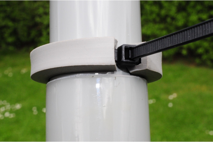
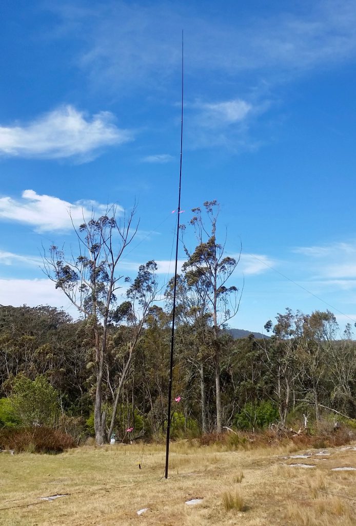
Recently I’ve been thinking more about the perennial problem of using squid poles as antenna supports – the fact they all too readily collapse into themselves. This is probably more of an issue with permanently set up poles, but it also can waste valuable operating time in the field. Insulating tape works for a while, but it removes protective paint from the pole and is pretty messy.
Only this past weekend I had set up my 7m squid pole near the small lighthouse at Henry Head on Botany Bay. The winds were so strong and constant I could have got away with not bothering to tether the distant end of my end fed half wave antenna, as it was blowing horizontally from the tip of the squid pole – just like the original end fed Zepp antenna would have looked behind the airship that gave it its name. But of course just as I was about to answer someone’s CQ, it collapsed!
For some years now – at home – I have used an idea that I think originated from Peter Bogner of DX-WIRE in Germany where he recommended using a cable tie nestled inside a square section rubber tube to secure the sections to each other. I have always assumed the cable tie and rubber sleeve are positioned at the overlap point between two adjacent telescoping sections of the squid, that is around the lower (and larger diameter section). This approach leads to a more resilient antenna pole which is more likely to survive windy weather, but it is by no means guaranteed to stay up indefinitely.
This is the rubber profile from DX Wire acting as a stop with a cable tie
I have just checked his site, specifically the page about this “rubber profile” and realised I have been using it incorrectly. His intention was to use these as “stoppers” and as a cheaper adaptation of the rubber padded stainless steel clamps of the larger Spiderbeam poles (see below) for shorter telescopic fibreglass poles.
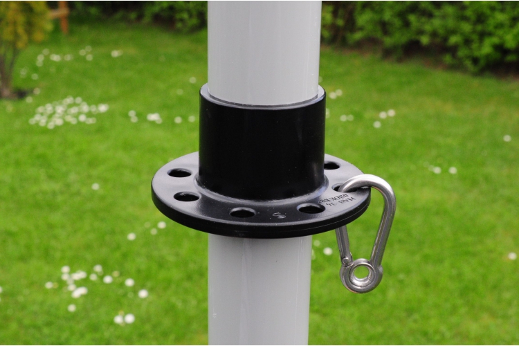
This is the MAB34 support plate that can be used to guy say a 7m squid pole
Peter Bogner’s DX-WIRE also sells a handy “support plate” that can be used on our 7m poles as a way of attaching guy lines to the pole at the handy height of about 2m from ground. It sells for 3.5 Euro including VAT.
I have been forced to think more about this topic after needing to re-assemble my collapsed 10m squid pole almost every week or two.
I happened to be looking at the Spiderbeam site and also looking at the DIY info to help build your own version of the spiderbeam antenna. I have also looked at their own more robust version of the squid pole, the Spiderbeam pole available in 12m and 18m!
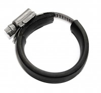
One of the rubber covered clamps used to keep the Spiderbeam 12m pole upright
The device of choice these days appears to be the pipe clamp or what the British call the Jubilee clip. The beauty of these clips is that they can be tightened and later if necessary untightened. Seems a little more sound than using up tens of long heavy duty cable ties every time I work on the pole. The clips also make it more practical to dismantle the pole in case of particularly high winds. This would be even easier if pipe clamps with butterfly handles were used in place of the screws.
The clips are available in stainless steel and feature a worm gear driven by a screw thread to adjust the size and pressure of the clip. Spiderbeam offer a set of clips for their Spiderbeam telescopic towers, 11 for the 12m pole. They are sold along with sections of rubber to be used underneath the metal band of the clip to protect the pole.
I have read elsewhere a recommendation to insert the metal band inside a piece of heat shrink for extra protection.
For me though recently, the main question about these clips has been where precisely should they be installed on the pole.
The Spiderbeam company’s advice is clearly to install them not at the overlap but around the thinner upper section to prevent it slipping into the lower section.
Simply put one clamp at the very bottom end of each tube segment and tighten the clamp. Here it will act as a stopper and prevent the tube from sliding downwards into the next bigger tube segment. The rubber padding is made of a thick flat rubber band, protecting the mast against any damage from the clamps.
This advice is quite a surprise to me. It makes sense only if it’s assumed that the pole has been assembled in the normal (?) way of extending the sections and tightening each of them before installing the clips.
On reflection the approach of using the clips more as a stop than a clamp makes more sense. I have always had qualms about compressing the outer tube against the inner tube when they are both rather rigid. The pipe clamps are able to exert quite a deal of compression but that would be unnecessary in the recommended ‘stop’ mode.
My next task is to measure the various diameters of each and every section of my 7m and 10m squid poles from Haverford’s and my 12m Spiderbeam pole, so I can obtain the most appropriate sized pipe clamps for them. TTS Systems, the Australian distributor of Spiderbeam, sells the clamp set for A$44. You can buy direct for 15.55 Euro but postage I think is a lot more.
UPDATE: I purchased the clamp set from TTS Systems. They were easy to assemble. The kit is the set of clamps, a 1.2m length of 3mm thick by 12mm wide rubber strap and black heatshrink to hold the rubber in place.
The completed set of clamps for the 12m Spiderbeam pole
In case you’re wondering – the pipe clamps / jubilee clips sizes for the 11 sections are:
40-60mm x 2, 32-50mm, 30-45mm x 2, 25-40mm, 23-35mm, 20-32mm, 16-27mm, 12-20mm, 10-16mm
As you can see from the photo you need to open the clamps out to install the protective rubber strip and the heatshrink. I suspect the larger, lower clamps are doing the most work.
I installed them on my Spiderbeam pole on a site in the southern highlands. It’s holding up a vertical for 40m, one of a number of antennas to be used in some upcoming contests. Returning after four weeks and strong winds, three of the lower sections had collapsed, so those clamps were tightened. I may have been too tentative/cautious on the initial installation.
Here is the 12m Spiderbeam pole enjoying a clear day in the southern highlands!
The definitive website on how to install the Spiderbeam fibreglass pole clamps is http://www.dj0ip.de/spiderbeam/fiberglass-spiderpole/clamp-sets/ where Rick DJ0IP from Spiderbeam-US explains all – including the advice to use a 7mm nut driver to tighten the clamps.
The other day I was pottering around Facebook and stumbled across an amusing story via BBC News I think about a young couple who had decided to set themselves the challenge of visiting every one of the over 2,500 railway stations across Britain. I later discovered it’s connected to a Kickstarter project and has a website http://allthestations.co.uk. Reading some of the comments to the video – always a risky activity – I discovered a reference to the videos made by Geoff Marshall (of the same couple) exploring the secrets of the London underground and another youtube video – via https://www.youtube.com/user/geofftech2 – where he talks about cassette tapes. He also has a website at http://geofftech.co.uk.
In the comments to this clip there were a number of pointers to another youtuber who focuses on old analogue technology called ‘Techmoan’ – https://www.youtube.com/user/Techmoan. One of the first videos of his I watched featured what Techmoan described as his holy grail of 1970s consumer electronics – something that featured both Nixie tubes and an oscilloscope to visualise the music – a bizarre old silver SAE hi fi amplifier you can see on https://www.youtube.com/watch?v=ZkCIdufSGS8.
About half way through the video he demonstrated the way the small oscilloscope worked. Normal music resulted in an animated but pretty fuzzy trace jumping about the screen. Then he put some different audio into the amp and the oscilloscope which resulted in regular geometric images appearing on the small screen. Quite amazing! I was aware of the neat regular waveforms that can be created with different frequency ratios on the X and Y plates. The Australian ABC’s logo was created by using a 3 to 1 ratio many years ago. But what I was seeing on the screen was lightyears beyond that.
He got a lot of comments pointing him to resources on oscilloscope music and a follow-up youtube video had pointers to a number of clips and sites, most notably Jerobeam Fenderson’s site at http://oscilloscopemusic.com.
a random screengrab from one of Jerobeam Fenderson’s piece for oscilloscope music – planets
Techmoan also provided links to an Oscilloscope Emulator for Windows, Mac & Linux https://asdfg.me/osci/ which works on my Mac and a Reddit Oscilloscope Music Page https://www.reddit.com/r/oscilloscopemusic/ with further links and info about this bizarre art form.
Jerobeam Fenderson also offers a program to create oscilloscope music called OsciStudio via his website.
My main project for at least the last 12 months has been building a solid magnetic loop antenna and its companion automatic loop controller. I’ve been roughly tracking its progress at my magnetic loop antenna project page on this blog.
As usual, life has got in the way, but I want to get back on track and complete the project. To start pumping some RF current through it again, over the weekend I spent a short time playing with the loop on WSPR on 40, 30 & 20m. The tests were too brief but they certainly confirm that the loop is capable of transmitting a signal in spite of the fact the loop is only half a metre above ground and surrounded by metal garden furniture, a steel framed awning and gutters.
I used the WSPR Beacon android app to control my transmitter. There was some discrepancy (tens of Hz) between the actual output frequencies on the app and those shown on WSPRnet. I also found that tuning the loop to each WSPR frequency using the iP30 antenna analyzer was easy and the KX2 gave lower SWR figures.
The brief test became an exercise in understanding theWSPRnet results taking into account propagation and loop orientation which was aligned north-south.
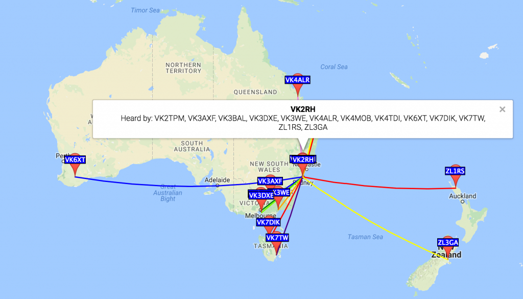
This map view combines all 20 spots of the 1W VK2RH transmissions from grid square QF56oc. The first test was logged at 2017-05-07 01:36 UTC. (I’ve trimmed repeated info from the chart below to improve its fit on the page.)
Time
MHz
SNR
Drift
Reporter
RGrid
km
az
05:24
14.097001
-15
1
VK4ALR
QG56fk
1151
356
05:24
14.097016
-26
0
VK4TDI
QG62lm
733
14
04:48
10.140109
-22
0
VK4TDI
QG62lm
733
14
04:48
10.140094
-23
0
VK7TW
QE37pc
1057
198
04:48
10.140091
-17
0
VK6XT
OF86td
3086
261
04:40
10.140095
-27
0
VK7TW
QE37pc
1057
198
04:40
10.140090
-4
0
VK3WE
QF32se
547
216
04:40
10.140090
-22
0
ZL1RS
RF64vs
2069
101
04:40
10.140092
-15
0
VK6XT
OF86td
3086
261
04:40
10.140091
-16
0
ZL3GA
RE66ho
2130
126
03:18
7.040121
-24
0
VK3BAL
QF22mc
711
230
03:18
7.040134
-7
0
VK3AXF
QF33fn
516
235
03:18
7.040135
-18
0
VK4MOB
QG62ol
734
16
03:18
7.040130
-18
0
VK3DXE
QF21nv
720
228
03:18
7.040128
-12
0
VK2TPM
QF56of
14
0
03:18
7.040129
-14
0
VK7DIK
QE38cu
918
207
01:36
7.040183
-16
-1
VK3AXF
QF33fn
516
235
01:36
7.040177
-16
-1
VK2TPM
QF56of
14
0
01:36
7.040184
-24
-1
VK4MOB
QG62ol
734
16
01:36
7.040179
-21
0
VK3DXE
QF21nv
720
228
40 metres favoured north-south, while 30 metres was literally an all-rounder and 20 metres was too brief. These results probably say more about propagation than the loop, not to mention the heavy lifting done by all the reporter stations extracting my down to -26 or -27 dB signals from the noise! Impressive all round!
About midway through January, I heard via a Sunday morning WIA broadcast that a group of ARRL Volunteer Examiners was offering to hold exam sessions at the Wyong Field Day at the end of February.
I passed my original amateur license exam here in Australia almost 40 years ago. My AOCP (Amateur Operator’s Certificate of Proficiency) says I passed a test on 21st November 1978. (That was probably the date of my second or third attempt to pass the morse at 10 wpm test.)
For the exam, I also had to answer questions about radio regulations and to demonstrate “a knowledge of wireless telegraphy and wireless telephony and electrical principles”, I had to write a number of essays about things like neutralizing a valve (tube) power amplifier or how a superheterodyne receiver works. A lot has changed since then. New technology like software defined radio and the internet.
After I heard that local hams were conducting US license exams here, my first resolution of the year was to pass the US exams for all three levels.
I was surprised that I was able to do this. All the FCC required was an online registration of an FRN (an FCC Registration Number) using a US address which was easy enough to obtain without having to pay a monthly fee. Also for the US, there is no license fee and licenses have a term of ten years.
With just on six weeks to prepare I planned to work sequentially through the three levels, spending more time on the hardest level, Extra. With no time to spare I ordered Kindle versions of the license manuals for all three levels. I also downloaded copies of the freely available complete question pools for each level. The exams are objective tests based on random selections from every part of all of the ten main exam topics – 35 questions for Technician and General, and 50 for Extra.
The license manuals essentially re-arrange the hundreds of disparate questions into a more or less flowing narrative about how to be a modern ham radio operator.
As I worked my way through the manuals I would mark up the questions and answers in my copies of the question pools and make notes if necessary to explain the answer.
The information in the manuals was very well presented and manageable and digestible. I loved the way liberal amounts of ham radio wisdom about operating practice was added to the mix. It was really like having your own personal Elmer guiding you through the intricacies of aspects of the hobby that previously were unclear or were new to me.
Best of all for me the study process demystified a lot of the mathematics of electronics and set me on a path to better understand what after all is the basis of the ‘magic’ of radio. I love the fact that the Scottish mathematician Maxwell concluded radio waves must exist, just from the maths, many years before they were actually discovered or produced by Hertz and others.
The ARRL web pages supporting the license manuals has links to a range of other resources including a page of references that pointed me to a really brilliant site which sets out to systematically (and enjoyably) explain the advanced maths to those whose school maths didn’t quite reach those dizzy heights, like me. It’s highly recommended if you want to delve deeper.
I’m happy to say I passed all three exams. I received an email from the FC about two weeks after the tests. There was no real need to do it, but it was a personal challenge – a little like voluntarily doing a driving test again, times three. It also turned out to be a convenient way to calibrate and update my ham radio knowledge.
The session was well organised and afterward, one of the VEs demonstrated how he uses his US call by connecting via remoteham.com on his iPad to a contest-grade station high in the hills in New York state. Amazing and fast! At rates around US$1 a minute, this must be a good way to turn a remote location into a source of revenue to be earned from the hordes of hams living in cities with a high level of local electrical noise.
Just read about Scandinavian versions of untranslatable concepts (like German’s gemütlich or Portuguese’s saudade) at Quartz.
One example is the Danish word hygge (pronounced ‘hooga’)…
There’s no direct English translation for hygge, but the word evokes both coziness and togetherness. “It’s not just cozy with a blanket and a glass of wine,” Kurtz tells Quartz. “It’s also interpersonally cozy—so having a few people with you talking about issues and things you care deeply about. Having some candles lit, maybe a nice warm drink in your hand. Feeling safe and content.”
The Norwegian equivalent is koselig.
Psychologists working at the University of Tromsø have found that those further north in Norway have more positive wintertime mindsets. Kari Leibowitz wrote a piece for The Atlantic explaining how people flourished there during winter.
It all helps explain the popularity of Dxing and SWL as a group activity as written about here a while ago.
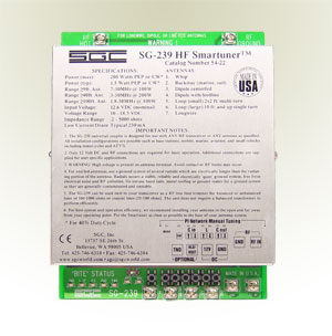
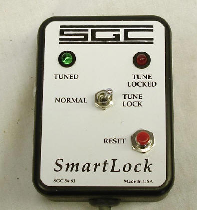
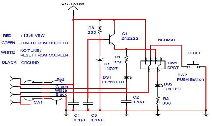
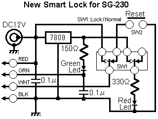
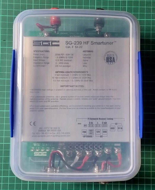
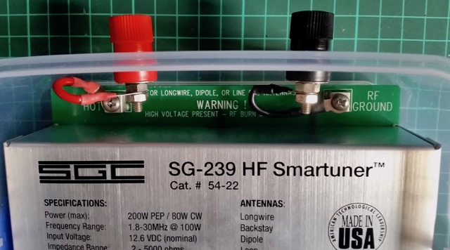
The Smartlock is an accessory for my SGC SG-239 HF Smartuner, and other ATUs they make. It can be bought ready made or built.
SGC SG-239 HF Smartuner witing for a weatherproof enclosure
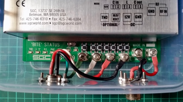
There are indicator LEDs that signal status (TND, l ‘Z’, 2:1, PHZ, FWD, Auto & Man) on the lower section of the PCB of the SG-239 but they are only visible near the unit. As they recommend mounting the unit in a weatherproof container and as close to the feed point as possible, it’s unlikely these will be useable except in testing and servicing.
For reference – here are the indicators and connections on the transceiver end of the SG-239:
B.I.T.E.* Status LED Descriptions – *Built In Test Equipment
TND This LED will light when the tuner has found an acceptable match. It will remain lit until conditions have changed which will cause the tuner to find a different match. (i.e. A new transmit frequency has been detected, or tuner has been reset.)
L ‘Z’ This LED shows the status of the antenna impedance. When lit, the impedance is 50 ohms or less. When off, the impedance is greater than 50 ohms.
2:1 This LED will light when the VSWR is greater than 2:1. It will extinguish when VSWR is less than 2:1.
PHZ This LED indicates the status of the antenna reactance. When lit, reactance is inductive. When off, reactance is capacitive.
FWD This LED indicates the presence or lack of RF power from the radio. When transmitting, the LED will light to indicate RF is being detected. In receive, the LED should be extinguished.
OTHER All LEDs will blink on and off at a rate of 2Hz to indicate the tuner was not able to find a valid match.
The LEDs are very small and quite faint and almost impossible to see on a sunny day.
As the ad below indicates the Smartlock provides two controls that can be used remotely from the tuner and close by the radio – allowing the operator to lock or stop the ATU constantly retuning as the load changes and to reset which forces a retune the next time a signal is transmitted.
The Smartlock also indicates if the ATU managed to tune the antenna and if the lock is on. The lock can be invoked when the antenna is to be used for receive or when there are too frequent changes in the physical environment of the antenna such as when mobile and passing trucks or going under bridges….
Installation requires normal coax and a four conductor cable for power and control.
—-
SMARTLOCK, FOR SG-230/237/239 SMARTUNER
$60.00
Catalog #54-63
The SmartLock provides two external controls for the SG-230/237/239 Smartuner. The locking function prevents retuning despite changing antenna loads. The reset function forces the coupler into a retune cycle the next time a signal is transmitted. Tune and lock status is indicated by one green and one red blinking LED. Supplied with 9 feet (2.5 metres) connecting cable. For use with SG-230/237/239 couplers manufactured after July 1, 1993, only.
Its simplicity and the cost of the assembled unit have inspired a number of people to roll their own.
The colour code of the cable to the Smartuner appears to be:
TND = Green,
HLD/RSET = White
+12V = Red
Gnd = Black
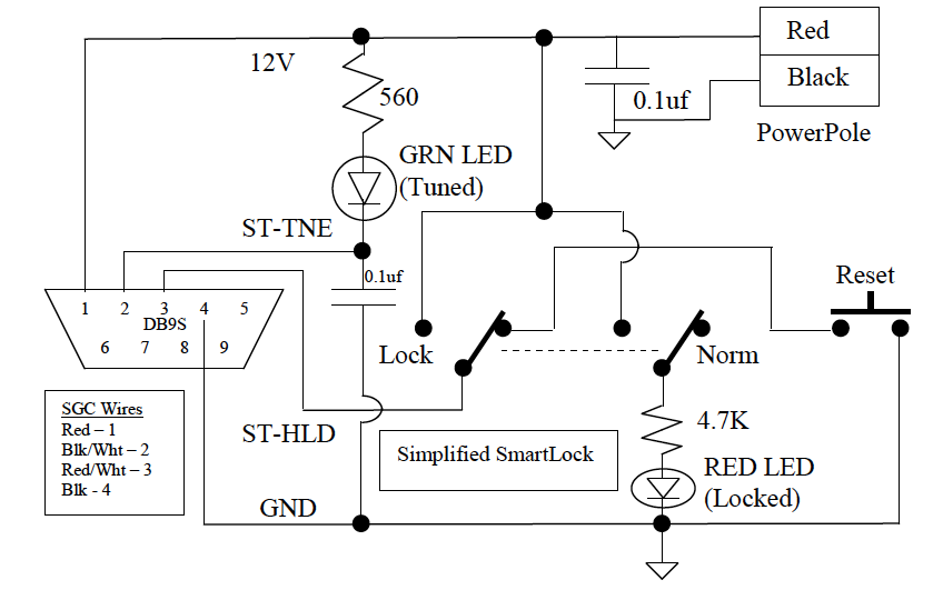
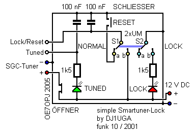
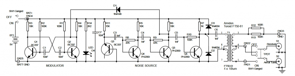
Simplified SmartLock
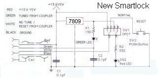
Phil Salas – AD5X – decided to remove the components making up the voltage regulator part of the circuit.
“I wanted to build a SmartLock to use with my SG-239. After studying the SmartLock schematic, I couldn’t figure out why SGC put in the transistor and zener diode. The ST-TNE input on the SG-239 is just a 1.5K resistor to an open collector transistor to ground. So I eliminated Q1, R3, D1 and C3 on the SGC SmartLock schematic. My final circuit is shown below. I used a DB9S connector to interface with the SGC tuner (I attached a DB9P to the tuner interface wires), and a PowerPole interface for 12VDC. This way I could use a standard DB9 extension cable as necessary for interfacing between the tuner and SmartLock. I used ultra-bright LEDs (3000mcd or so) to provide plenty of visibility.”
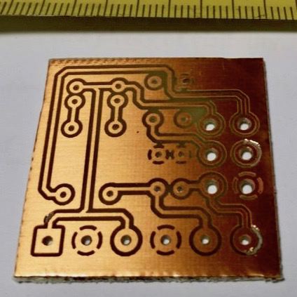
This uses a tiny PCB available on Italian eBay from a seller who wanted 50 € to send one to Australia!
I worked out a way to use a scrap of veroboard to hold the two capacitors and one of the resistors and to manage the wiring between the base and the panel of the enclosure which is probably more efficient and certainly faster. As well I noticed that the PCB seems to be designed for a different kind of DPDT switch where the centre poles are not in the centre!?! So I can add the satisfaction of saving whatever Euros I would have ultimately paid to the greater satisfaction of having nutted out the layout of the veroboard scrap…
Luca used the simplified circuit by Hans Nussbaum DJ1UGA which appears to have in turn have some subsequent input from OE7OPJ (who by the way has a very interesting website at http://www.qth.at/oe7opj/).
L’accordatore automatico SGC-239 indubbiamente è un gran bello strumento. Si collega e funziona ottimamente con qualunque radio (HF) semplicemente utilizzando un cavo coassiale e una fonte d’alimentazione a 12 volts. Non è particolarmente esoso di corrente e anche in utilizzo SOTA non va a gravare sull’autonomia giornaliera. Ne ho trovato uno usato sui soliti canali nazionali ad un prezzo decente e non mi sono fatto scappare l’acquisto. Accorda davvero di tutto gestendo potenze da 1,5 a 200 watt. Ottimo per il mio Yaesu 817, ma altrettanto utile per le “normali” radio munite dei canonici 100 watt. Per poterlo però utilizzare al meglio, si rende necessario l’acquisto di un interfaccia che permette di resettare o bloccare lo stato d’accordo del SGC-239. Tale interfaccia (SMARTLOCK) si trova però in vendita a quasi 100 euro, decisamente troppi per 2 condensatori, 2 resistenze, 2 led e un paio di interruttori. La prima idea è stata quella di prendere lo schema presente sul manuale dell’accordatore e realizzare su basetta forata il circuito. Cosa questa realizzabile, ma che avrebbe dato un idea di “precarietà” a tutta la realizzazione. La scelta a questo punto è ricaduta su un mini circuito stampato realizzato con maestria da Danilo Cramaglia (lo trovate su Ebay come utente Martelloman), che partendo dallo schema elettrico mi ha consegnato quanto riportato in foto:
The SGC-239 automatic tuner is undoubtedly a very nice tool. It connects and works well with any radio (HF) simply by using a coaxial cable, and a power source to 12 volts. It is not particularly power hungry and even practical to use on a routine SOTA outing. I found one used on the usual national channels at a decent price. It really suits around handling power output from 1.5 to 200 watts. Great for my Yaesu 817, but just as useful for “normal” radio equipped with 100 watt “cannons”.
But in order to make the best use, it is necessary to obtain an interface that allows you to reset or block the status of the SGC-239. This interface (SMARTLOCK), however, is for sale at nearly 100 euro, far too much for 2 capacitors, 2 resistors, 2 LEDs and a pair of switches. The first idea was to use the circuit in the tuner’s manual and build it on perforated board. While this is feasible, it could give an idea of “insecurity” to the whole creation. Instead I chose a mini PCB made with skill by Danilo Cramaglia (Ebay-user Martelloman), which, starting from the wiring diagram handed me what is reported in the picture:
I plan to use this wiring arrangement for the 4 pin plugs, socket and line.
In the hand book to the SGC SG237 Auto Antenna Tuner there is a circuit for an interface they call the SmartLock and it allows some manual control over the AATU and more importantly, it indicates when the tuner has tuned successfully.
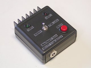
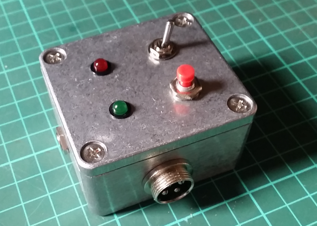
The shielded 4 core wire is clamped in the cable tie through a pull through bushing. The case uses a diecast aluminum box TD 5-8-3B (55x30x80) by TAKACHI. The front of the enclosure has the Normal / Lock switch (2-pole, double-throw), the Tuned LED (Green), the Locked LED (Red) and the Reset switch (Make contact). It includes the three-terminal regulator. The bypass capacitors on the circuit diagram are omitted here.
(3) box overview and operation
Once tuning is complete the Tuned LED (Green) glows. If the Normal / Lock switch is pointing to the right, the Lock side, the Lock LED (Red) is lit and fluctuating SWR, etc. does not cause automatic re-tuning.
If the switch is set to the Normal side, normal operating conditions prevail, the SG-239 will automatically start tuning if SWR or the band is changed.
If you press the RESET (red) button, the ATU will re-tune.
For some good ideas about how to protect the SG-239 see http://dg6hd.darc.de/html/sgc-239.html. He uses a large-ish electrical junction box and includes windings on toroids…
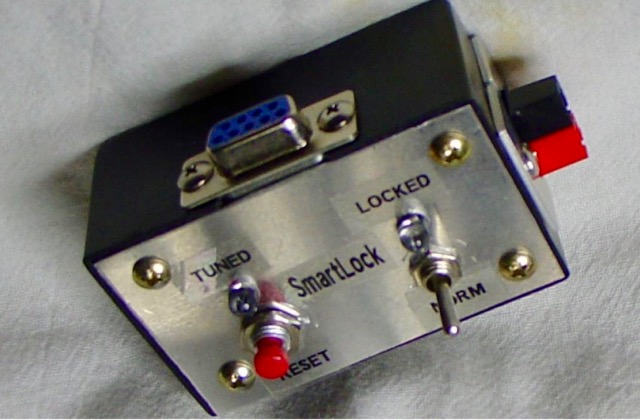
>So here is my effort successfully completed today…
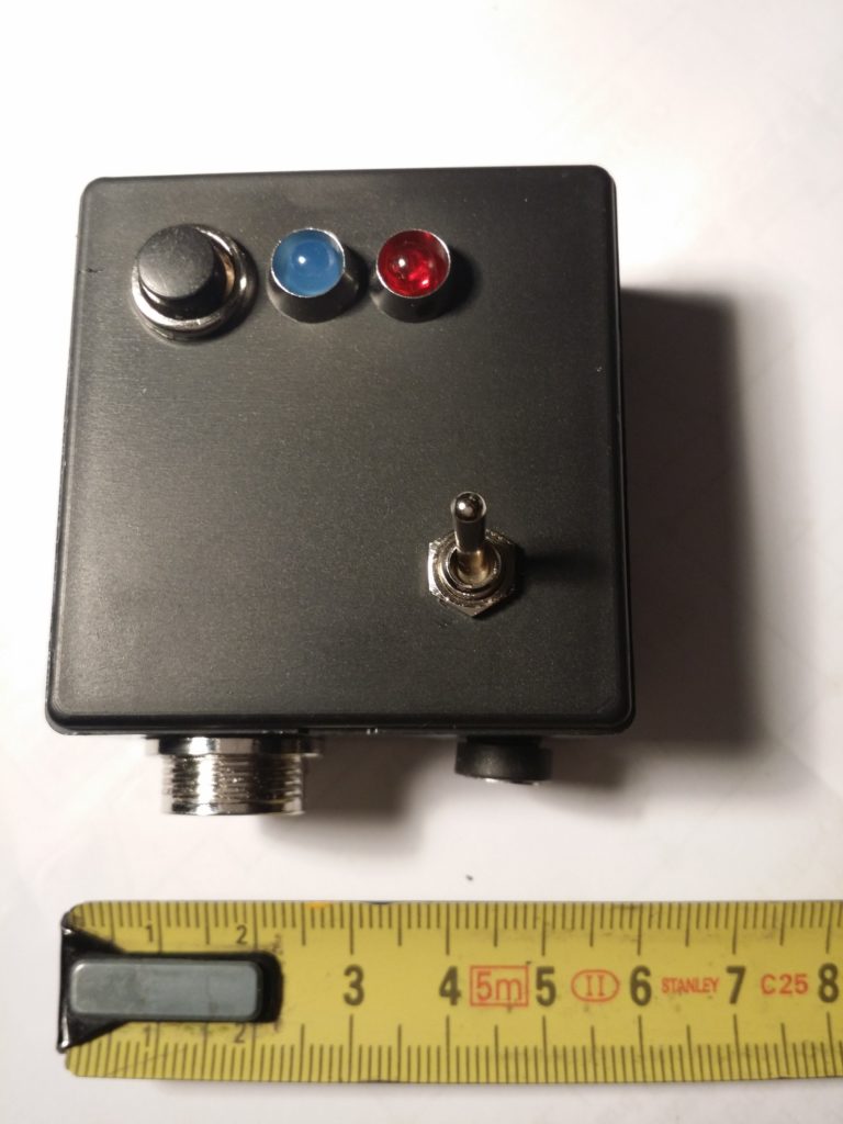
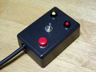
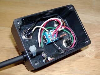
I used the simplified circuit by Hans Nussbaum DJ1UGA and the front panel layout of Phil Salas AD5X. I managed to squeeze everything into a compact package – a small die cast aluminium enclosure 64 x 58 x 35mm which Jaycar sell for $9.95. And that was the main cost. Everything else was on hand.
I’ve yet to label the panel, but the green LED indicates a successful tune, the red LED is on when the switch is in the Locked position, and the push button switch is the reset. I used 4 pin sockets and line plugs to connect to and power the Smartuner. And I used a DC socket to supply 12V power. I had planned to use power poles but decided that would not fit comfortably in this small enclosure.
The ATU is housed in a plastic lunchbox which can be protected by a larger rubber waste paper bin as recommended in the SGC manual.
Great moment this afternoon when the Automatic Loop Controller fired up as it should. Happy days.
The Automatic Loop Controller PCB and display
When I first fired it up, after loading up the Arduino program, all I could see was a dull green glow on the screen. It wasn’t until I remembered a comment from another builder about adjusting the potentiometer on the PCB that controls the LCD contrast.
It was a great relief that my slow and deliberate build – double checking all component values and joints – paid off. Next step is to build the SWR bridge and connect to the stepper motor on the loop.
Also finally managed to make a plate out of perspex to mount my stepper motor on to the supporting bracket on the magnetic loop after much mulling over how to achieve a suitable level of accuracy with my dremel drill press to get the stepper shaft as close to the centre as possible.
The clear perspex mounting plate is sitting above the white plastic mounting bracket with holes for three support struts.
Not too bad for a cut with a straight baby hacksaw. The key tool turned out to be my old school compass which had scribing points fitted which were perfect for marking out the perspex. I figured that these ‘cross hairs’ would help orient and centre the piece and the shaft. After these shots I countersunk the holes. If it looks a little skewiff, that’s probably because it is!
Success – part 2
Also successful today getting this instance of the blog back online using AWS. Another steep but satisfying learning curve about the nitty gritty of DNS management! What’s in a CNAME? you might ask.
Midway through building my version of Loftur Jónasson – TF3LJ / VE2LJX‘s Automatic Loop Controller, I came across Leigh Turner’s impassioned plea to consider this noise bridge antenna tuning design mentioned on page 32 of the “Overview”. As a concluding note VK5KLT states that he considers “The perceived need for a slick and salubrious auto-controller for properly tuning an MLA is oftentimes overrated and exaggerated, IMHO”.
He argued that elaborate microcontroller aided automatic loop tuning circuits are unnecessary and people should consider using this more covert and considerate approach. I think the bridge could be an excellent idea and a simpler way of staying in tune as you change frequency for all sorts of antennas. For a magnetic loop, it still requires a way to remotely adjust the tuning capacitor.
“The circuit goes inline between the rig and the antenna and sends a gated broadband noise signal to the antenna using a directional coupler and a noise bridge. You just listen on the desired operating frequency and watch your RX S-meter for a sharp dip whilst adjusting the loop tuning capacitor.
You simply remotely tune the loop with the aid of the receiver S-meter while you are on the wanted frequency without keying up and TX power output. This makes tuning a breeze without having to move off frequency and have the TX put out any RF power.”
VK5KLT mentioned the MFJ-212 Matchmaker that uses this same approach (and which is still on the MFJ catalog at US$99.95) and also referenced ZL3KB’s April 2001 RadCom article (pp17-21) as an easy and more economical way to replicate the same functionality.
“The distinguishing merit of the novel gated coupler/noise bridge loop tuning method is it’s completely passive and covert in operation; you don’t transmit any TX power whatsoever to attain an optimal loop tune setting. The technique makes for fast, QRM free, safe and easy QSY shifts and netting a frequency.” Leigh Turner adds that it’s even simpler if you use a pan adaptor or a modern SDR receiver as you can see the sharp null on the screen of the band scope display.
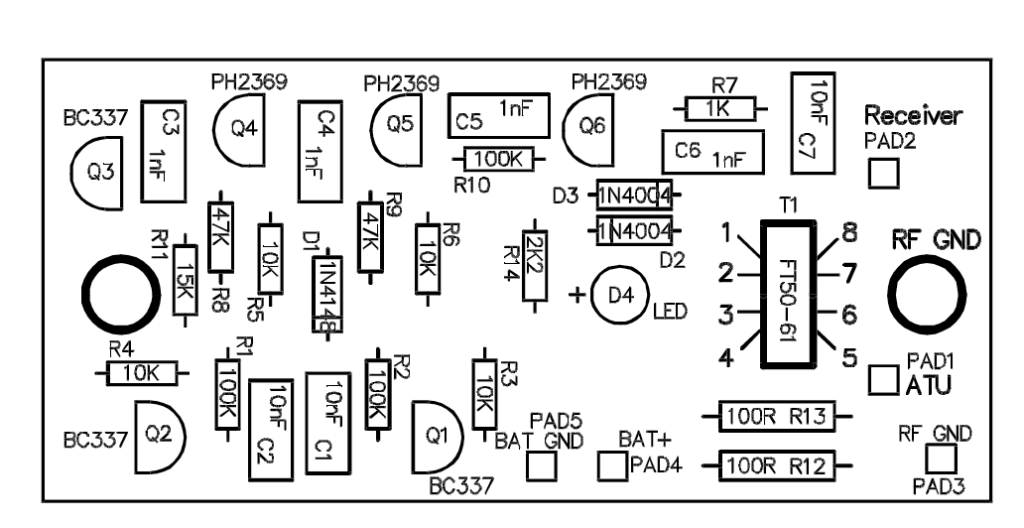
Kelvin Barnsdale ZL3KB’s RadCom article describes building and using the wide band noise bridge as a silent antenna tuning indicator. These four pages include circuit, PCB design and layout and full details of BOM and balun/transformer construction.
On 14 May 2001 ZL3KB published a 4-page follow-up pdf document “Instructions for Antenna tuning Noise Bridge” with info supplementary to the RadCom article about construction and operation. This article has an updated circuit and parts layout and refers to an issue B of the PCB. The new board includes places for the LED and dropping resistor R14, and pads for the two 100Ω load resistors and the two diodes D2 & D3.
This is the updated circuit with some updated values.
This indicates parts placement with the updated PCB.
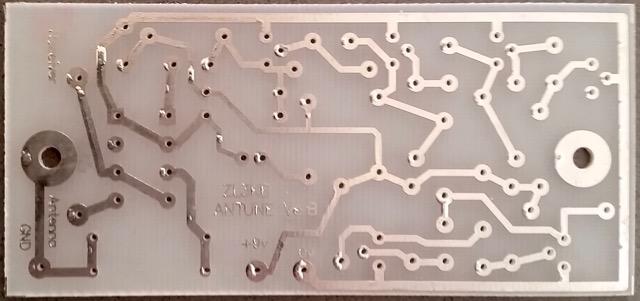
Here is the foil side of the updated PCB
I contacted Kelvin Barnsdale and was lucky enough to obtain the PCB above.
I was meandering around the web this morning and stumbled on to a page where famous key collector and curator Tom Perera W1TP had re-created the morse key setup used by Walter Winchell to introduce and punctuate his radio and later TV broadcasts. They were a pair of Vibroplex bugs.
The Vibroplex ‘Lightning Deluxe’ and ‘Original’ bugs
I grew up in Sydney in the 1950s and remember how radio station 2UE would start their news bulletins with a brisk CQ CQ. They were probably inspired by Winchell. Another memory is watching ‘The Untouchables‘ on TV with narration by Walter Winchell.
Ironically in his early years as a gossip journalist he was close to prominent criminal identities and later became friends with J. Edgar Hoover. He was Jewish and in the lead up to the second world war was one of the first Americans to criticise Hitler and those in the US who supported him. Another of his targets was isolationist Charles Lindbergh. His fame followed his reporting the famous kidnapping and subsequent trial.
From the clip you can hear the rapid-fire delivery. In many ways it’s like a precursor to much of what we consume today.
Walter Winchell reporting – from a brilliant site about old mics – coutant.org
He attacked the Klan and its supporters. After the war he aligned himself with the Senator Joe McCarthy’s hunt for communists. But within this short clip there are a couple of places where he briefly questions a couple of issues that were to haunt the US for the next couple of decades – Vietnam and cigarettes and cancer.
Complex and probably unattractive, what I want to know is if he actually knew how to handle those Vibroplex keys.
I spent the pleasant sunny part of the final day of autumn testing a vertical antenna for 80 metres using Buddipole parts for home.
The back garden space here is barely 4 metres by 4 metres and for the moment the chimney is out of reach. While I have dreams of a magnetic loop for 80m, the vertical is more in reach now.
Plan for 80m vertical made from Buddipole components
I installed a counterpoise wire a few feet shy of 66 feet length hidden on a timber fence that runs down the side of the property. The idea is to connect a short fly lead to connect the hidden counterpoise when the antenna is deployed and then disconnect when it’s all packed away. Buddipole components don’t lend themselves to permanent installations. The counterpoise doesn’t follow the recommended dog leg arrangement and is higher off the ground than the 2 feet suggested.
The purpose yesterday was to establish how speedily the antenna could be assembled and adjusted for a frequency of interest such as a net.
Here’s a list of the items used along with the counterpoise:
9′ telescopic whip 2 x 22 inch antenna arms low band coil + clip VersaTee Buddipole short mast Buddipole tripod Balun
I was surprised how easily it all went together. The adjustment wasn’t as fiddly as I expected such a short antenna for this band would be, and it appeared to give a usable bandwidth.
The Buddipole Low Band coil showing the coil tap for 80m
Assembly was straightforward. Set up the tripod and mast with only bottom two sections telescoped out. Attach the Versatee horizontally to the top of the mast. Connect the Low Band coil. Leave the red fly lead loose for the moment. Attach two 22 inch antenna arms to a long whip antenna fully extended. Then carefully attach that assembly to the top of the Versatee. I also connected a 1:1 balun between the Versatee and the iP30 SWR Analyser.
The next step is to simply drag the fly lead across the coil turns to identify the best spot to tap the coil. Background noise level rises as you get in the zone. I used the iP30 SWR analyser to narrow it down to a spot 16 turns up from the base of the coil.
This means I was shorting out the bottom 16 turns of the coil. The adjustment is too coarse on a turn by turn basis. You appreciate the value of being able to tap at 1/8 of a turn increments. (The coil is on an octagonal former.)
It took me a few measurements to realise that as I progressed left (from my point of view) I was decreasing the amount shorted out and hence increasing the loading inductance and so lowering the resonant frequency. It’s actually more confusing reading that sentence than understanding it in practice!
My target frequency was 3535kHz and this is a chart of the SWR readings I had when the coil tap was set at what I calculate to be 15 3/4 turns up from the base of the coil.
frequency
SWR
frequency
SWR
3505
1.8:1
3550
1.1
3510
1.6
3555
1.1
3515
1.4
3560
1.1
3520
1.3
3565
1.2
3525
1.2
3570
1.3
3530
1.1
3575
1.4
3535
1.0
3580
1.5
3540
1.0
3585
1.6
3545
1.1
3590
1.8
The magic spot for my 80m vertical
The 1.0:1 bandwidth was 10 kHz while at 1.5:1 it was in excess of 65 kHz.
From readings at the other possible coil tap points my guess is that at this frequency range each face of the coil moves the resonant frequency by about 4 kHz. One thing to be aware of with the Buddipole hardware is not to accidentally short out adjacent turns of the coil with the coil clip. It’s hard to do but I managed and it will throw your readings.
Next step of course is to make some contacts or at least activate the antenna on WSPR or JT65 to get an idea of whether the signal gets over the fence.
From checking the chart on page 146 of the ‘Buddipole in the Field’ book by B. Scott Andersen, NE1RD, I estimate that my shorting tap at about 16 turns from the base means I’m using about 39-40 uH of loading to achieve resonance at 80m. So that’s a starting point if I wanted to build a more permanent and cheaper vertical installation.