Every day I seem to relearn the wisdom of the old saying – “if it ain’t broke, don’t fix it!’ – and how it truly applies to reassembling equipment.
Here are the immediate tasks I’m addressing as components arrive:
Ask myself how I managed to install the touchscreen upside down!?! Or to put it another way – turn the whole front panel upside down and put controls upside down on the wrong side of the display?!? Luckily it’s a simple fix (Menu 3 > System Config > Invert Touchscreen)
Reconnect Raspberry Pi and the touchscreen and the fans on the Pi to confirm all working as before disassembly for drilling work on front & rear panels. All good!
Success! – Portsdown updated software and sent a testcard across the world via the internet. Now for the RF.
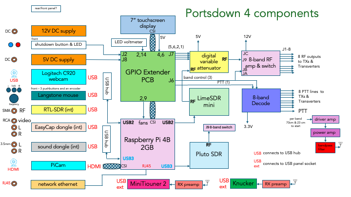
Plan how to implement 5V distribution wiring for all devices needing it – all (including of course the Raspberry Pi, to be fed from the XL4016 DC-DC power supply module (purchased from Mini Kits in Adelaide) set to deliver 5V from 13.8V via the Anderson Powerpoles on the rear panel. These include:
power for LCD touchscreen (via Raspberry Pi GPIO?)
Ras Pi fans (via the Raspberry Pi GPIO?) These two items simply require some way of extending the connections to the relevant pins on the GPIO PCB. (I’ll make “bespoke” dupont style leads with slightly heavier wire with appropriate connectors.)
a voltmeter display to confirm and monitor the voltage setting of the XL4016 PSU module – to deliver the appropriate voltage to the Raspberry Pi (5.1 or 5.2V). I’ll probably attach this near the PSU module as I’m not sure this small display warrants a presence on the front panel but we shall see… (This will depend upon how much the output varies depending upon the different 12V supplies that might be used.)
small 5V fans for Pluto & LimeSDR Mini enclosures? I’ve seen recommendations to do this on the BATC forum, and presumably if you’re blowing cooling air into a small enclosure, there needs to be a way for the warmed up air to escape?
two perhaps larger 50mm fans on the side walls of the main Portsdown enclosure??? Perhaps I need first to devise some way to monitor temperatures within the enclosure as the project progresses. This will have some bearing on the way I orientate the PSU module and its heatsinks.
Plan how to connect all the USB connected devices
PSU module to directly power the Raspberry Pi via J8 on GPIO, and two USB hubs, one powered directly from the PSU module 5.1V out, the other via one of the Pi’s USB sockets.
Raspberry Pi to power directly via GPIO: the LCD touchscreen display, the 2 x Pi fans and then via one of its own USB3 ports > the Adalm Pluto
C920 webcam – via the USB2 socket on the rear panel connected to the USB hub
Audio dongle – via microphone and headphone sockets on front panel to dongle on to USB hub
Video dongle – via three RCA sockets on rear panel through to Video Capture dongle connected to a USB hub
LimeSDR Mini – via direct connection to a USB hub
Langstone “mouse’ tuning encoder etc – via a connection to a USB hub
RTL-SDR dongle – via SMA or BNC connector on rear panel on to dongle and then to a USB hub
Now that there’s a switch and an LED on the front panel, install the shutdown circuitry as outlined on the schematic for the orginal GPIO break out PCB and omitted from the later one.
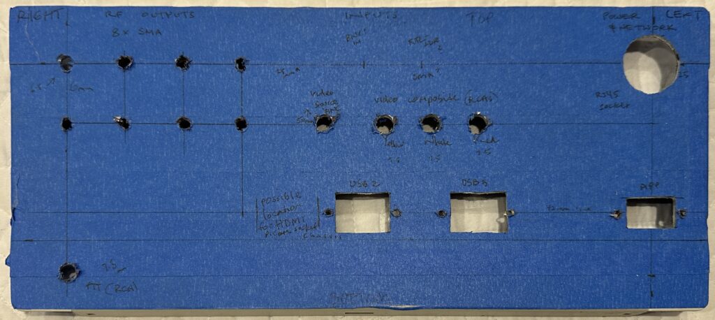
After quite a lot of time thinking through what my plans might be for the specific bands and modes with the Portsdown 4 I’ve spent a few hours over a couple of days drilling and nibbling holes in the panels. When I first built it a couple of years ago I only managed to make the cutout for the 7” touchscreen and install a sheet of aluminium in the closure to act as a chassis to mount the Raspberry Pi.
I am now – almost – able to connect it up and put the lid on it. I’m also finally installing the shutdown components for the Pi. I still have to work out how to mount one of the DSI to HDMI PC boards on the chassis and against the panel to enable a PiCam to be connetced via a regualr HDMI cable. This will probably involve a piece of aluminium to hold the tiny PCB and HDMI socket against the rear panel.
The beauty of it all is that once the process has some momentum, things can move quickly.
The marked up and drilled and nibbled rear panel of my Portsdown 4 build demonstrating how urgently I need to invest in a drill press!
I’m glad I was able to spend some time planning both the front and rear panels’ layouts. But I’m sure there’ll be many re-thinks and more probably, mistakes along the way, in spite of all the planning and thinking!
Traditionally ATV and its associated analog 7 MHz bandwidth has been restricted to UHF and microwave bands, and bandplans have reflected that. With the global emergence of DATV and RBTV (reduced bandwidth TV) experimentation is now taking place on lower bands, down as far as 10m.
Alongside conditions about qualifications, licences, callsigns and electromagnetic energy exposure, there is a schedule detailing “Permitted frequencies and limits on operation” organised in terms of licence type – Foundation, Standard or Advanced.
The main national organisation of Australian radio amateurs, the Wireless Institute of Australia last updated its detailed 32 page bandplan in September 2020.
In contrast the recent handful of pages listing permitted frequencies and limitations indicates a light touch administration that may well enable innovation on the bands especially above 28 MHz and future proof the management of these bands. (But of course legislation and band plans are different documents with different purposes.)
Above 52 MHz there are no bandwidth limitations on amateur transmissions.
The limitation imposed on transmissions on 10 m is
If a person operates an amateur station with an emission mode that has a necessary bandwidth exceeding 16 kHz, the maximum power spectral density from the station must not be greater than 1 watt per 100 kHz
from Tables B & C, Schedule 2 Radiocommunications (Amateur Stations) Class Licence 2023
And the limitation on the 50-52 MHz segment of 6 m is
A person must not operate an amateur station with an emission mode that has a necessary bandwidth exceeding 100 kHz
from Tables B & C, Schedule 2 Radiocommunications (Amateur Stations) Class Licence 2023
It will be interesting to see how different groups of amateur users negotiate a coordinated way to use the bands, and still maintain freedom for technical innovation for such modes as RBTV and DATV and whatever else might emerge in the future.
I imagine anyone building a Portsdown DATV setup in Australia like I am right now, should consider bands beyond 70 cm & 23 cm. Exciting times.
I’ve been building bits and pieces of what will become a digital amateur TV capability for just on five years! I lost my momentum after building a number of components and it’s only in the last few weeks I’ve found a renewed enthusiasm to get on with it!
One of the main prods has come from watching the weekly DATV net on VK3RTV. Anyone anywhere can watch this either live via this BATC streamer link or via Ian VK3QL’s YouTube channel. The net attracts an energetic and skilled group who easily sustain a fast paced 60 minute video conversation. It’s very smoothly presented with lots of visual variety and useful information and very few technical hiccups. The Melbourne DATV amateurs seem to have a very professional sense of time and audience interest and keep the show moving.
My other inspiration is the weekly BATC Oscar 100 net scheduled for 8pm Thursday which is either 6am or 5am(!) on Friday morning here in eastern Australia. I’m trying to work out how I might record it off the streamer while I sleep. This international net happens over the brilliant geostationary satellite QO-100 whose footprint unfortunately doesn’t include Australia, but it does appear to have boosted interest and activity in satellite communications and DATV in Europe. If I set the alarm I can watch this BATC net via the BATC streamer .
This is the first result of my planning the build of my Portsdown 4. I’m sure it will change over the next few weeks. It’s also to help me work out which controls and connectors might go where on the front and back of the enclosure. I actually find this thinking very enjoyable.
A few weeks ago at the ARNSW Dural site I was talking with Mark Blackmore about the classic radios incorporated into the VK2WI broadcast building. He showed me some beautiful Collins receivers and some Racal sets. Also occupying a position on the equipment rack was a very shiny Kingsley AR7, the famously unauthorised copy of the National HRO receiver produced to supply the Australian Army and the RAAF during the second world war. (I later found a detailed description of the story behind the restoration of what I believe is this actual radio model at Ray Robinson’s website http://www.tuberadio.com/robinson/museum/AR7/)
Mark looks after disposal sales for the ARNSW and he had tales of beautiful radios that he had inspected over the years that had been stored in less than ideal conditions. His advice in a nutshell – At the very least just wrap the radio up in a large plastic garbage bag!
This sent a guilty shudder down my spine as I remembered a couple of radios I had acquired a very long time ago that had lived in various storage sheds and cupboards over the decades. But it also prompted me to have a proper look at them over the next week.
Back in the late 1980s I had bought what I thought was an AR7 from a ham in western Sydney. It also had a complete set of plugin coil boxes. I’m ashamed to confess that since buying it I had never once really examined it to check out its condition. I had downloaded copies of the schematic and the operation manual and even the series of articles from Amateur Radio magazine detailing the various modifications many VK hams made to their AR7s in the 1950s and 60s, but I obviously hadn’t gone further. Even more obviously to me now, I hadn’t even read the first few pages of the manual. If I had I might have realised that I had one too many coil boxes!
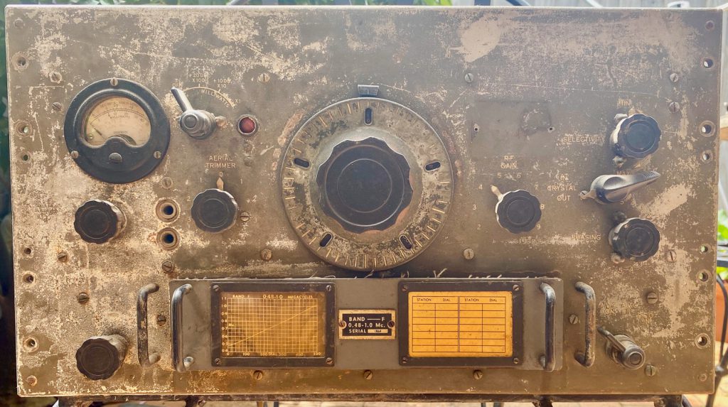
As soon as I started a new web search into what I thought was my AR7 I realised there were some important differences. While it shared the distinctive HRO style dial, my radio had a different front panel and layout of controls. It was nothing like the shiny stainless steel I could see everywhere. In fact the best indication of what the original finish might have been was in a patch where the boiler plate identification of the radio would have been had it not been removed for some reason. The coil boxes looked quite different as well with small charts under yellowing plastic rather than engraved in the faceplate.
The front panel of my AMR100 looking like it’s been neglected and crying out for some TLC.
Thanks to some excellent websites about military radios, it didn’t take long to discover the actual identity of my receiver.
Dave Prince VK4KDP via the Royal Signals website https://www.royalsignals.org.uk/photos/vk4kdp.htm confirms the radio I have was in fact made by AWA and was probably painted an attractive green. It’s an AMR100. AMR stands for American receiver as they were made for the US Signals Corps.
On his own page at https://www.qsl.net/vk4kdp/army.html you can also see a very attractive version of how my radio should appear. Note the AWA logo on the US Signal Corps boiler plate, and the green front panel.
Apparently the AMR100 Receiver was manufactured by AWA in Sydney under licence from National. I’ve read elsewhere that the US Signal Corps in the South West Pacific were having difficulties obtaining HROs from the US and AWA offered to supply them in a form of a reverse lend-lease arrangement.
Dave VK4KDP describes the AMR-100 as “a Single Signal type covering 480 kHz to 26 MHz with 6 plug-in coil boxes”.
Armed with this information I was able to locate two detailed operating manuals for the AMR 100 (the ‘table top’ model) and the AMR101 (the rack mounted version) on Ray Robinson’s encyclopedic site at http://www.tuberadio.com/robinson/Manuals/
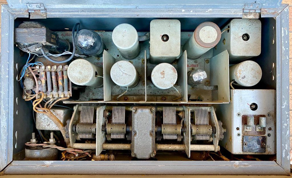
My particular radio includes the same team of valves, two 6U7G RF stages, a 6J8G mixer, a 6J5G oscillator, two 6U7G IF stages, a 6G8G multi-tasking as detector, AVC and AF amplifier, a 6J5 BFO and a 6V6G as AF output.
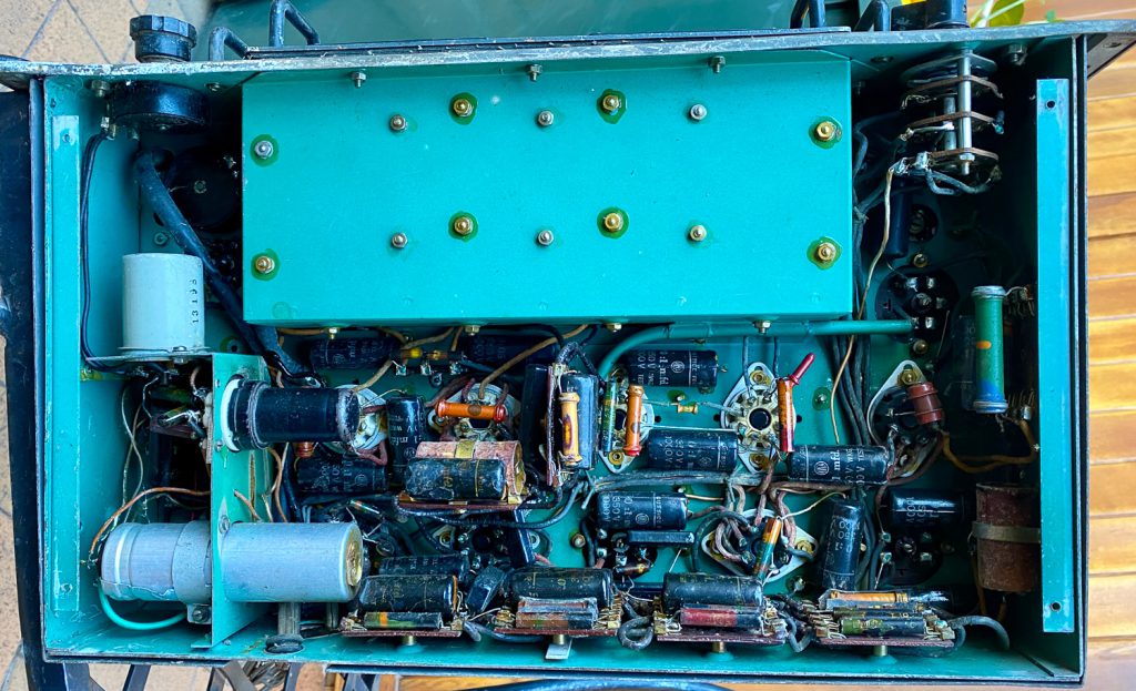
The inside of the AMR100 showing added output transformer on top LHS hiding the power supply mod on LHS and missing crystal on RHS
Once I had a closer look inside the radio it was apparent that a few modifications had been made to the receiver. Where I imagine the 6J5 BFO was originally located – based on markings on the painted chassis – is now occupied by a 5Y3GT which looks like part of an added power supply. The BFO is re-located on a bracket installed beneath the chassis using a metal 6J5 valve.
I suspect the 455 kHz crystal has been removed. I have to check whether an FT243 style crystal might fit. It may need some kind of adaptor.
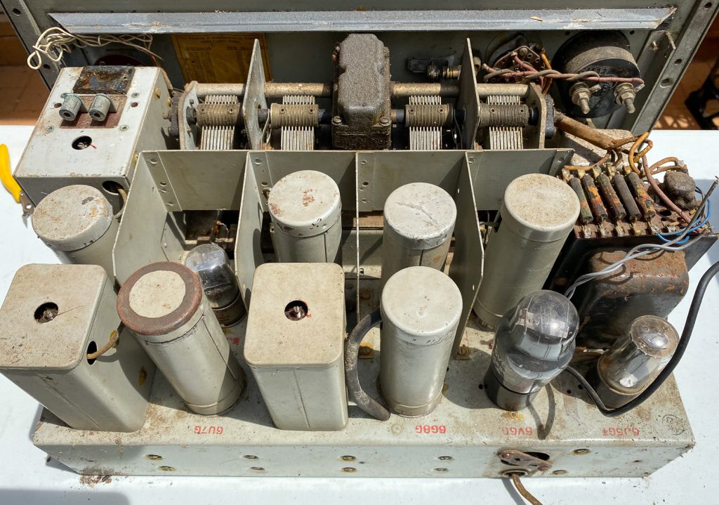
Underneath the chassis of the AMR100 showing the general condition of components and wiring. The black metal 6J5 valve for the BFO can be seen on the lower LHS near the BFO inductor.
Once tidied up the chassis is remarkably clean, top and bottom. Some of the valves bulbs have come loose from their bases. All the valve screens are present and seem okay.
The was a shot of the AMR100 chassis after it was removed from its case and before any cleaning
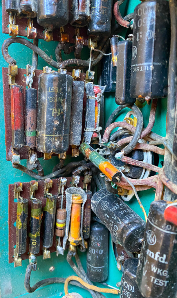
Overall the condition of the wiring is probably the main cause for concern. The rubber covering is now brittle and much has broken away from the wire. It looks as if it will all need to be replaced. I expect all the paper capacitors and electrolytic capacitors will need to be replaced.
A closer view under the chassis of the AMR100 showing the condition of the wiring and the vintage and condition of the components
If I don’t keep the 240 VAC power supply modification I will need to find or build a separate power supply capable of delivering about 270 VDC at 75 mA and 6.3 V at about 3 A. That shouldn’t be too difficult.
I suppose the first stage of assessing what to do next (and even whether) to restore the receiver is to check the continuity of all the inductors.
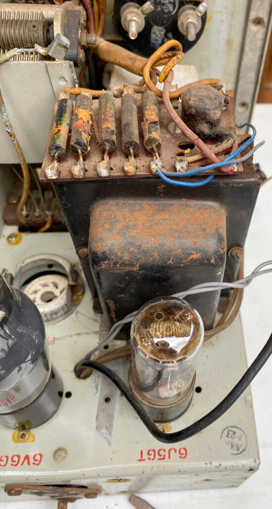
After removing the speaker output transformer the power supply modification can be seen with the 5Y3GT valve where the 6J5GT BFO valve was originally installed. The tag strip of resistors above the transformer are for setting the various ranges of the front panel meter.
This is the day I joined the BATC which must surely be one of the best value amateur radio groups in the world. They produce a professional colourful quarterly journal CQ-TV with top quality practical technical articles and manage a growing global community of amateur TV enthusiasts. The BATC has become a focus for effort to take advantage of emerging technologies to generate quality digital TV signals at affordable costs and to explore the practical limits to reduced bandwidth to deliver still usable DATV signals, even over HF!
The BATC hosts a detailed frequently updated members’ wiki with full information about DATV formats, hardware, software etc. It’s at https://wiki.batc.org.uk/BATC_Wiki.
There is also a busy forum site at https://forum.batc.org.uk/ for help, information and the interchange of ideas.
Like all great amateur radio clubs they source and supply components and essentials for their DATV projects. I have started building the Portsdown DATV Transmitter and the MiniTiouner Receiver.
Hams living in the UK, Europe and Africa are also able to take advantage of the DATV facilities of the QO100 satellite. But even from distant Australia, we can at least watch the BATC QO100 DATV net live every Thursday night at 8pm UK time (generally 6am Friday in Eastern Australia) at https://batc.org.uk/live/oscar100net which is full of focused technical discussion about DATV with occasional diversions to railways and antique carriage clocks!
Our small group of CW ops and learners meets on a weeknight on air but have found it hard to find a band that works for all of our group. The logical choice of 80 or 40 is considered out of the question for the apartment dwellers. So we’ve looked at using the upper HF bands on the assumption that they can erect relatively stealthy antennas for the net and dismantle them afterwards.
We seem to have had some success with 15m. But signals are still pretty weak given how relatively close to each other we are. We are in three general areas in the city – the north shore, the eastern suburbs and the inner west.
One of the group suggested we might enjoy stronger reports if we all settled on the same polarisation of our signals and all used a vertical antenna for the net.
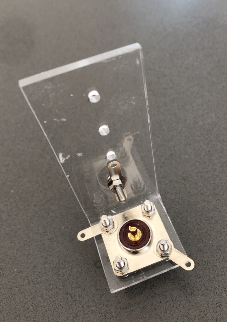
So here is my attempt at a simple connector. Our leader Skip suggested the most effective way to make a vertical is to first tune the radials to your Centre frequency before adjusting the vertical element.
There is no strain relief for the radials but this construction makes tuning the radials a possibility by simply re-locating one of the radials on to the nut and bolt assembling the vertical part of the Perspex bracket.
And today is a perfect sunny Sydney winter’s day to be outside messing with antennas!
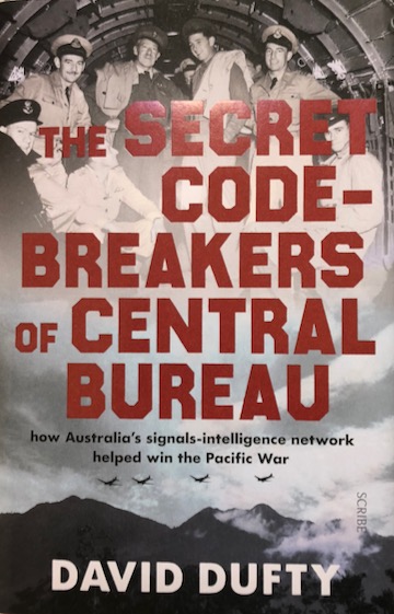
On Wednesday evening I went along to a talk at a nearby library by David Dufty about his recent book ‘The Secret Code-Breakers of Central Bureau – How Australia’s signals intelligence network helped win the Pacific War’ published last year by Scribe.
The Secret Code-Breakers of Central Bureau by David Dufty
It’s a great story that does uncover previously unacknowledged contributions. Dufty’s interest was sparked by a newspaper mention of Australian wartime code-breaking on Anzac Day 2012. His interest triggered a comprehensive research trail.
It’s a great read with a solid bibliography. He interviewed about twenty people who worked on breaking the Japanese codes. From a standing start, the operation grew to involve over 4,300 Australians – a venture, Dufty says, it’s hard to imagine us being able to mount as readily today.
He mentioned many of the characters from Australia’s early radio history, including Mrs Mac, Florence MacKenzie, who trained thousands of women morse operators who in turn were used to train many Australian servicemen.
He also mentioned Eric Nave who was responsible for breaking Japan’s Naval codes. Nave as a young naval cadet had spent years in Japan learning the language and culture of the country.
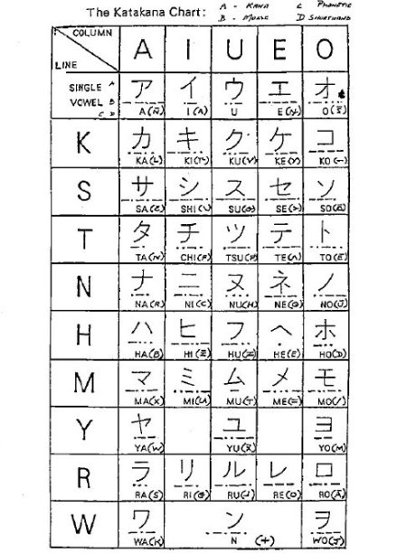
The character with the best nickname would have to be Keith ‘Zero’ Falconer. He was the country’s top interceptor of Japanese Kana coded messages. He got the nickname from his colleagues as every single day of Kana code training in Melbourne he would score zero errors in the test. Japanese hams can still be heard conversing in this code on the bands today.
Japanese Kana or Wabun morse code
The character who stands out from David Dufty’s talk on Wednesday evening is Stan or Pappy Clark. Apparently, prior to enlistment, his work was scripting radio serials for children. The mention of the magic word radio was enough to catch the eye of people recruiting for radio intelligence work, and it turned out to be a fortunate selection for Australia.
Stan Clark used his talents to develop a comprehensive knowledge of the Japanese communication networks and was able to analyse the dynamic ebb and flow of their radio traffic. Even if we weren’t able to decode every message the broad overview – which Dufty interpreted as the ‘metadata’ of the enemy’s radio communication – of this traffic analysis played a crucial role in determining the allied strategy of the war and effectively saved thousands of allied and enemy lives. Macarthur’s famous island hopping strategy was directly informed by this intelligence. One of the special things about Wednesday night was that unknown to Dufty until the end of his talk, Clark’s grandson and family were in the audience.
I’ve been wondering whether I should try to synchronise my most recent efforts at learning and improving my morse with a similar complementary neural mapping exercise of simultaneously learning to touch type as I practice copying morse code.
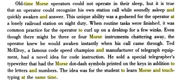
I was googling around – on the off-chance someone had developed the ultimate piece of software which combined G4FON Koch CW Trainer with Typist or some other touch type trainer, oh and for the Mac would be good – using the term “learning morse and to touch type at same time” and I discovered via Google Books Lewis Coe’s ‘The Telegraph’. Here on page 109 is mention of how operators could recognise their call in their sleep!
The highlighting is due to the google search term.
On pages 69-70 there’s mention of how the older operators used a mill to take down messages as they streamed in over the line.
Maybe the best approach would be to change the learning sequence of characters to match the character sequence of touch typing so that every character gets a double whammy of learning reinforcement. So F, J, D, K, S, L, A and ; (?) instead of K, M, R, S, U, A, P, T, L and O.
It shouldn’t be too hard to generate suitable static mp3 audio files of the touch type progression of characters. It would be great if there was a way to randomly generate according to this new progression, in a similar way to the G4FON software, with the alternate character sequence.
Also, I’m sure someone somewhere must have considered the learning pros and cons of such an approach.
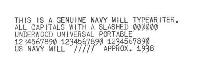
I also found the perfect font to use. It’s called MILL
Using WSJT-X as my example digital program, here are the steps to getting digital modes to work with the K3 using an external sound card, the ASUS U7.
The process is almost identical to the one I use with the KX3, an external soundcard dongle and a MacBook Pro.
First, it is simple and easy to adjust and repeatable.
Connections:
Line in on the K3 rear panel is connected to the Headphones socket on the front of the Asus U7 (using red patch cord with ‘Line in’ label).
Line out on the K3 rear panel is connected to the Microphone socket on the front of the Asus U7 (using black patch cord with ‘Line out’ label).
RS232 on rear of K3 is connected via USB adaptor to unused USB connector on the PC.
USB socket on rear of Asus U7 is connected to another USB connector on PC. (this also provides power for the Asus U7).
software:
Asus (Xonar U7 Audio Center) to confirm selection of Headphones and Line-In, and to adjust levels
WSJT-X File > Settings or F2 >
General tab: Enter your callsign and grid square
Radio tab: Select Elecraft K3/KX3 in Rig drop-down list
Set serial port to same COM Port number revealed when you are using
Elecraft K3 Utility (But both programs cannot be run at same time)
Set baud rate to 38400
Data bits 8 Stop bits One Handshake None
PTT – select CAT Port should be USB
Transmit Audio Source is Rear/Data
Mode is Data/Pkt
Split Operation is set to Rig
Use Test CAT and Test PTT button to confirm correct connections. CAT will turn Green and PTT Red after clicking, indicating all is well.
Audio tab:
Under Soundcard select the appropriate option from the drop down lists:
Input – ‘Line (2-Xonar U7)’
Output – ‘Headphones (2-Xonar U7)’
Under the Reporting tab you can enable or disable uploading of spots to PSK Reporter and linkages to other programs include logging software.
Under the Frequencies tab – if you find there are no frequencies listed for the different modes, position cursor in the Working Frequencies window and right click and select ‘Reset’. This should populate the window with all the frequencies.
Use the PC’s regular audio device controls or the soundcard’s controls to adjust input and output levels. For example WSJT-X likes to have the green input bar graph on the lower left of the application window indicating about 30dB. Adjust the Headphones level to achieve this. I operate routinely with it hovering between 30 and 60dB.
The K3 is particular about the level of ALC on its transmit signal. You can use the microphone level to easily achieve the Elecraft ideal of 4 solid bars with the fifth bar flickering. This ensures a clean splatter-free signal.
Other aspects you need to consider with applications such as WSJT-X include installing an application to keep the PC clock accurate, as well as eventually checking frequency alignment.
I’ve spent the last couple of weeks spending some continuous and focused time finally getting some consistent results out of my radios using digital modes, especially WSPR and JT8 using WSJT-X.
Like everything else I do with ham radio, they reveal the woeful inadequacy of my antennas here. In fact, one of the benefits of WSPR is, in fact, the information it yields that provides some useful and comparable data about your antenna performance. The great thing about WSPR is that the worst antenna still seems to manage to generate some data so that any subsequent ‘improvements’ can be evaluated.
I have yet to find a document that helps you understand what the numbers especially the SNR actually mean. If you hear a signal at 0dB via WSPR does that imply that a CW signal at the same power output or some number of dB power increase would also be able to be copied? These kinds of questions are what leads me to think that there would be high interest in this kind of information. Even if there isn’t that potential market, it’s still an idea worth pursuing out of personal interest. I’d also like to read an explanation of what the variation of SNR numbers from the same station indicate about changing ionospheric conditions etc – what is significant, and what is within the range of normal statistical variation.
I’d love to know how to really make use of the data gathered by WSPRnet. What techniques do people use to manipulate and analyse the data? Also, there are presumably assumptions that need to be tested or acknowledged. Many people running a WSPR beacon leave the radio and antenna untouched – so it’s a constant – but others might explicitly be using WSPR to run tests of new antenna equipment so that the antenna is changing and not a stable element. I have been using it for exactly this over the last few days and noticed a significant increase in the number of reports and the quality of the signals reported in response to an extra metre in height of an antenna over the comparable time of day. But maybe the changes are within the range of normal day-to-day variation – especially at the current low phase of the sunspot cycle.
But I’m confident that a consistent user would be able to make some pretty reliable assumptions based on extended observations about what beacons could be considered constant if only from their numbers over the months. It would be great if there were some functions developed that could be accessed online on the WSPRnet site to analyse numerical qualities and features of the more consistent and reliable beacon stations. It would require some computer grunt I suppose to host these server-side processes which might be beyond the budget of the current setup. Whenever the number of concurrent users exceeds 120-140 the WSPRnet site regularly seems to crash and takes quite some time to recover.
It would be great to gather info on the different ways people use WSPR data. How much do professional space weather researchers use the immense volumes of data now being generated? I understand that Australia’s Space Weather Services staff do use it. As I write this WSPRnet announces it has counted over 952 million spots and is adding over a million every day!
I would love to see how people have used data gleaned via WSPR to generate views of how propagation changes during the day for different bands, or how to synthesise the same data into an informative comparative analysis of antenna systems.
Sotabeams DXplorer system – sold as part of the WSPRlite package – performs some interesting analysis of the WSPR data to generate logarithmically(?) scaled graphs of the distance of WSPR reports. It would better if somehow the formula underlying any comparison was able to also take into account the different power levels used.
I would also like to have a concise explanation of frequency calibration. The material K1JT includes was authored almost a decade ago. I’m unsure whether the latest versions of the application accommodate these procedures. I suspect they do as there is a need to do it. I am noticing a deviation in my reported frequency cored to what I calculate it should be. It’s quite out of the ballpark. Similarly, the variation amongst ‘reporters’ is relatively wide. Simple and direct advice about how to deal with this and fix it would be great.
There’s probably still some room to think about more ways to exploit the potential of the massive group of users for various types of experiments investigating propagation etc. Using the different modes it’s amazing how they can illustrate the variety of space weather behaviour. Earlier tonight while using FT8 on 20 metres, I saw the band suddenly go blank. It was as if the antenna had been disconnected. It recovered a little later.
Also, different ways of using the applications – especially WSPR – can lead to quite different impressions about what is actually going on. Running WSPR in band hopping mode in late evening creates the impression that there is no activity at all across those bands. However locking the system onto one band – 40 metres here – reveals a deeper level of ongoing activity that the thinner sampling of the band hopping mode misses representing.
At a more nitty-gritty level, I would like to know how best to use the different modes. Gary Hinson G4IFB/ZL2IFB’s FT8 Operating Guide is very clear. The mainWSJT-X User Guide seems to me to be more about the program rather than practical information about using it. It seems to assumes a high level of background and technical familiarity. I suppose I’d prefer documentation that describes explicitly and in a good level of practical detail how people are using the applications. I think it’s brilliant that the WSJT-X application is available for MacOS and Linux as well as Windows and even for the Raspberry Pi!
I wonder how far away we are from radios – kit or commercially produced – that are designed just for FT8 and nothing else. I think Adam Rong – a seller of QRP kits and radios developed and built in China – is about to offer such a radio.
As someone who has spent an inordinate amount of time *not* managing to get digital modes to run on my radios for a long time, I am delighted that in the last few weeks I have been able to get three of my Elecraft radios to successfully decode. It all seems so simple to me now, so that I can’t understand the barrier was before. Well, I think it may have been what I’m writing about here – the lack of suitably written documentation. What got me off on a successful run was a very simple PDF file about running sound card digimodes on the KX2 using a cheap soundcard dongle. It also took into account the Macintosh – so my first success was using the KX2 and my MacBook Pro. It was totally simple and easy to migrate the whole approach across to a KX3 when I wanted to run that much more power. Watching the PA temperature on the KX2 rise during a WSPR transmission – getting up to 53 degrees C on 2 watts – was exciting. I then substituted the Asus Sonar U7 sound card in place of the dongle. And then when I wanted to crank up the power a bit more for FT8, I migrated over to the K3. It was very satisfying to be able to adjust the Power slider in the WSPR mode to get the four solid bars of ALC with the flickering fifth. Also to get a clear sense of the actual level of the signal in that was required to get the decodes to start appearing.
At the moment I’ve been snatching data from the WSPRnet reports, taking a snapshot of the map view of my transmissions over say a day, and also taking snapshots of HamCAP each hour of the day’s propagation predictions for that band.
Well, the replacement stepper controller chips arrived early this morning. Didn’t take too long to replace them and connect everything up for a test.
The good news is that after a slight adjustment of VR2 the stepper appeared to be controlled by the rotary encoder. It made the right noises.
Try as I may, I wasn’t able to carry out the initial setup procedure as outlined by Loftur. I couldn’t find a peak in the noise.
After applying a portable SWR analyser directly to the loop when I thought I was at the lowest frequency point the loop would tune, I discovered there was a dip around 23 MHz! I was nearer the other extreme of what I think this loop’s range should be. So I’m thinking I may have the stepper motors wired wrongly with the result that the stepper goes in the opposite direction to what the controller thinks it should be.
After switching one pair of wires at the controller end, the stepper made a terrible noise as it hit the end of the capacitor’s travel. Checking it tentatively it didn’t seem to distinguish between clockwise and counterclockwise movement of the encoder. Whatever you did, the stepper turned in the same direction.
Time for further closer inspection of the wiring around the newly re-oriented common mode chokes and their associated bypass capacitors. This kind of behaviour may have something to do with a missing or failed connection in this part of the circuit.
Stepper only appears to turn CCW which turns the VVC CW. I’m now hoping the glitch is pretty obvious in this part of the board or associated wiring.