A few weeks ago at the ARNSW Dural site I was talking with Mark Blackmore about the classic radios incorporated into the VK2WI broadcast building. He showed me some beautiful Collins receivers and some Racal sets. Also occupying a position on the equipment rack was a very shiny Kingsley AR7, the famously unauthorised copy of the National HRO receiver produced to supply the Australian Army and the RAAF during the second world war. (I later found a detailed description of the story behind the restoration of what I believe is this actual radio model at Ray Robinson’s website http://www.tuberadio.com/robinson/museum/AR7/)
Mark looks after disposal sales for the ARNSW and he had tales of beautiful radios that he had inspected over the years that had been stored in less than ideal conditions. His advice in a nutshell – At the very least just wrap the radio up in a large plastic garbage bag!
This sent a guilty shudder down my spine as I remembered a couple of radios I had acquired a very long time ago that had lived in various storage sheds and cupboards over the decades. But it also prompted me to have a proper look at them over the next week.
Back in the late 1980s I had bought what I thought was an AR7 from a ham in western Sydney. It also had a complete set of plugin coil boxes. I’m ashamed to confess that since buying it I had never once really examined it to check out its condition. I had downloaded copies of the schematic and the operation manual and even the series of articles from Amateur Radio magazine detailing the various modifications many VK hams made to their AR7s in the 1950s and 60s, but I obviously hadn’t gone further. Even more obviously to me now, I hadn’t even read the first few pages of the manual. If I had I might have realised that I had one too many coil boxes!
As soon as I started a new web search into what I thought was my AR7 I realised there were some important differences. While it shared the distinctive HRO style dial, my radio had a different front panel and layout of controls. It was nothing like the shiny stainless steel I could see everywhere. In fact the best indication of what the original finish might have been was in a patch where the boiler plate identification of the radio would have been had it not been removed for some reason. The coil boxes looked quite different as well with small charts under yellowing plastic rather than engraved in the faceplate.
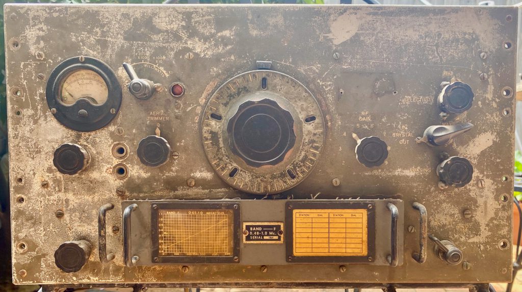
Thanks to some excellent websites about military radios, it didn’t take long to discover the actual identity of my receiver.
Dave Prince VK4KDP via the Royal Signals website https://www.royalsignals.org.uk/photos/vk4kdp.htm confirms the radio I have was in fact made by AWA and was probably painted an attractive green. It’s an AMR100. AMR stands for American receiver as they were made for the US Signals Corps.
On his own page at https://www.qsl.net/vk4kdp/army.html you can also see a very attractive version of how my radio should appear.
Note the AWA logo on the US Signal Corps boiler plate, and the green front panel.
Apparently the AMR100 Receiver was manufactured by AWA in Sydney under licence from National. I’ve read elsewhere that the US Signal Corps in the South West Pacific were having difficulties obtaining HROs from the US and AWA offered to supply them in a form of a reverse lend-lease arrangement.
Dave VK4KDP describes the AMR-100 as “a Single Signal type covering 480 kHz to 26 MHz with 6 plug-in coil boxes”.
Armed with this information I was able to locate two detailed operating manuals for the AMR 100 (the ‘table top’ model) and the AMR101 (the rack mounted version) on Ray Robinson’s encyclopedic site at http://www.tuberadio.com/robinson/Manuals/
http://www.tuberadio.com/robinson/Manuals/AMR100.pdf – a scan of the manual for the desktop model – AMR100 Receiver Type C13500. Ray Robinson refers to it also as US Signal Corps SC-CD-136-43.
http://www.tuberadio.com/robinson/Manuals/AMR101.pdf – which is a version of the manual for the AMR101 Receiver Type C13500R retyped by John Kidd.
I also located a scan of the original AMR101 manual at https://bama.edebris.com/download/awa/amr101/amr101.
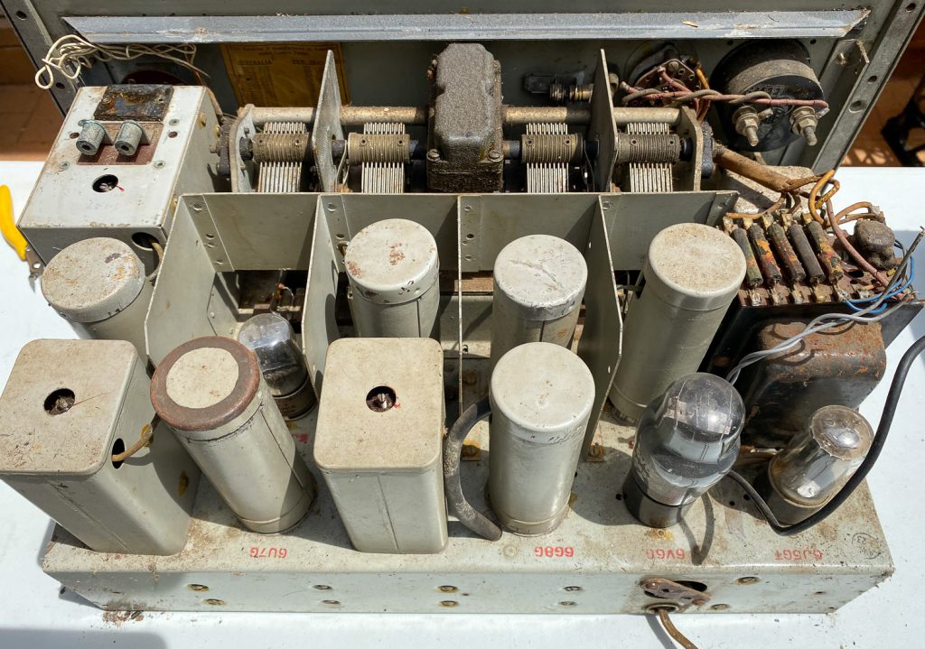
My particular radio includes the same team of valves, two 6U7G RF stages, a 6J8G mixer, a 6J5G oscillator, two 6U7G IF stages, a 6G8G multi-tasking as detector, AVC and AF amplifier, a 6J5 BFO and a 6V6G as AF output.
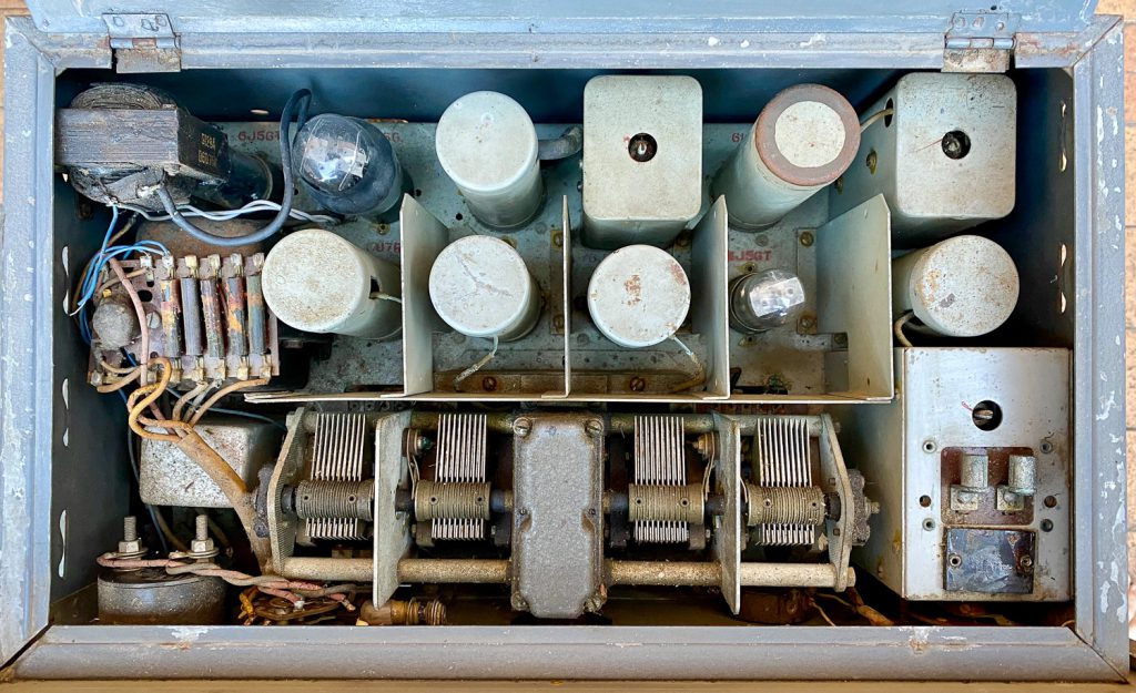
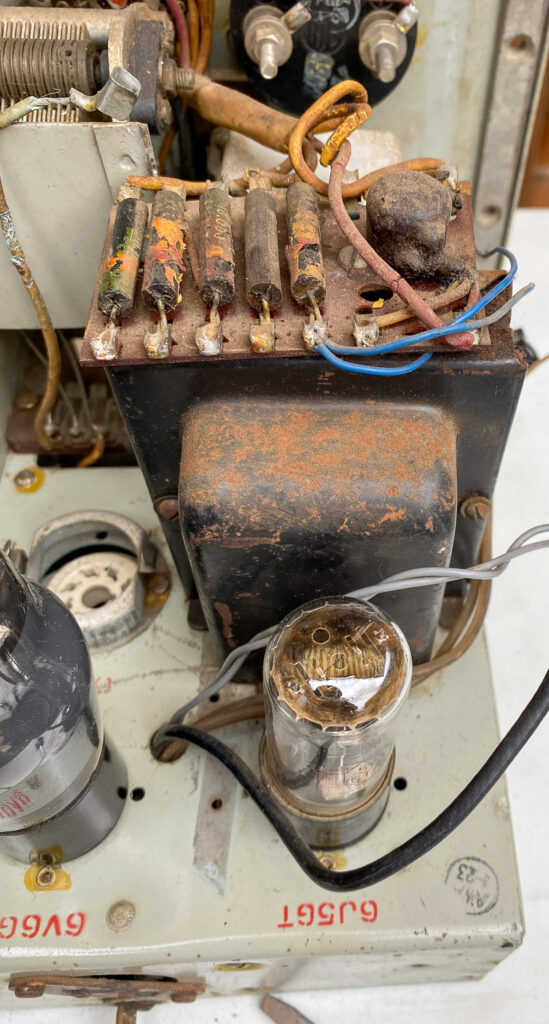
Once I had a closer look inside the radio it was apparent that a few modifications had been made to the receiver. Where I imagine the 6J5 BFO was originally located – based on markings on the painted chassis – is now occupied by a 5Y3GT which looks like part of an added power supply. The BFO is re-located on a bracket installed beneath the chassis using a metal 6J5 valve.
I suspect the 455 kHz crystal has been removed. I have to check whether an FT243 style crystal might fit. It may need some kind of adaptor.
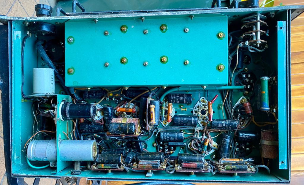
Once tidied up the chassis is remarkably clean, top and bottom. Some of the valves bulbs have come loose from their bases. All the valve screens are present and seem okay.
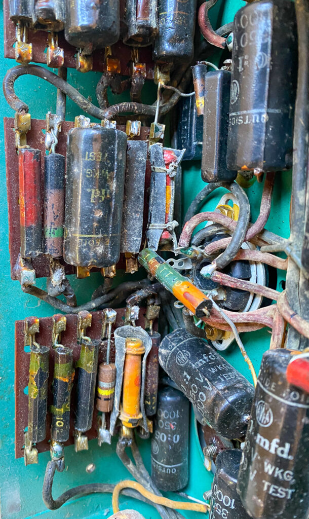
Overall the condition of the wiring is probably the main cause for concern. The rubber covering is now brittle and much has broken away from the wire. It looks as if it will all need to be replaced. I expect all the paper capacitors and electrolytic capacitors will need to be replaced.
If I don’t keep the 240 VAC power supply modification I will need to find or build a separate power supply capable of delivering about 270 VDC at 75 mA and 6.3 V at about 3 A. That shouldn’t be too difficult.
I suppose the first stage of assessing what to do next (and even whether) to restore the receiver is to check the continuity of all the inductors.
Leave a Reply