Our small group of CW ops and learners meets on a weeknight on air but have found it hard to find a band that works for all of our group. The logical choice of 80 or 40 is considered out of the question for the apartment dwellers. So we’ve looked at using the upper HF bands on the assumption that they can erect relatively stealthy antennas for the net and dismantle them afterwards.
We seem to have had some success with 15m. But signals are still pretty weak given how relatively close to each other we are. We are in three general areas in the city – the north shore, the eastern suburbs and the inner west.
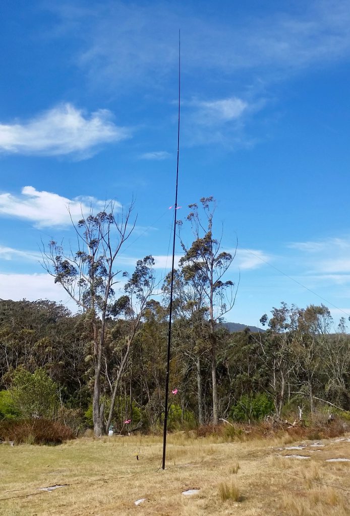
One of the group suggested we might enjoy stronger reports if we all settled on the same polarisation of our signals and all used a vertical antenna for the net.
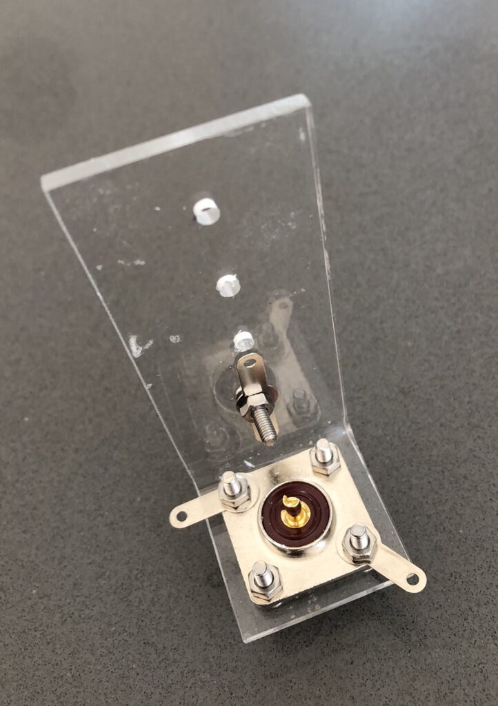
So here is my attempt at a simple connector. Our leader Skip suggested the most effective way to make a vertical is to first tune the radials to your Centre frequency before adjusting the vertical element.
There is no strain relief for the radials but this construction makes tuning the radials a possibility by simply re-locating one of the radials on to the nut and bolt assembling the vertical part of the Perspex bracket.
And today is a perfect sunny Sydney winter’s day to be outside messing with antennas!
Well, the replacement stepper controller chips arrived early this morning. Didn’t take too long to replace them and connect everything up for a test.
The good news is that after a slight adjustment of VR2 the stepper appeared to be controlled by the rotary encoder. It made the right noises.
Try as I may, I wasn’t able to carry out the initial setup procedure as outlined by Loftur. I couldn’t find a peak in the noise.
After applying a portable SWR analyser directly to the loop when I thought I was at the lowest frequency point the loop would tune, I discovered there was a dip around 23 MHz! I was nearer the other extreme of what I think this loop’s range should be. So I’m thinking I may have the stepper motors wired wrongly with the result that the stepper goes in the opposite direction to what the controller thinks it should be.
After switching one pair of wires at the controller end, the stepper made a terrible noise as it hit the end of the capacitor’s travel. Checking it tentatively it didn’t seem to distinguish between clockwise and counterclockwise movement of the encoder. Whatever you did, the stepper turned in the same direction.
Time for further closer inspection of the wiring around the newly re-oriented common mode chokes and their associated bypass capacitors. This kind of behaviour may have something to do with a missing or failed connection in this part of the circuit.
Stepper only appears to turn CCW which turns the VVC CW. I’m now hoping the glitch is pretty obvious in this part of the board or associated wiring.
Finally found some time to re-orientate the two transformers. I decided to remove the eight bypass 10nF capacitors to give my soldering iron more wriggle room to remove the transformers. The solder on the transformer pads needed some encouragement – in the form of more molten solder – to loosen up. This allowed me to use solder wick to take away most of what was holding them in place. The corners of the transformer are pretty fragile and would not tolerate much heat. Wasn’t too hard to lift them. Much more complicated was cleaning up the holes where the eight capacitors had been. I managed to destroy one of the pads. Decided to stop destroying the PCB and to re-install the bypass capacitors on the other side of the board.
I was actually able to use most of the capacitors I had removed and checked every connection a couple of times at least, especially a couple of the tiny pads for the caps that are near the larger choke pads.
Soldered the transformers back in properly this time, again checking every step over and over again.
After re-orienting the common mode chokes……and replacing the caps on bottom of the PCB to avoid damaging fragile pads.
Taking a few deep breaths now and having a break before reassembling the whole device and connecting it to the radio and the loop for the moment of truth and to find out if the A4975 stepper driver ICs can come back to life after having both their two outputs accidentally connected together! Normally they are connected across one of the stepper motor windings.
——
Well, because there is still no response from the stepper motor, the answer, unfortunately, is no, they probably need replacement. At least this time they’re not red hot. I have a pair of A4975 chips due to arrive sometime on Monday. Essentially $4.90 a pop, no shipping charge.
And reading the datasheet on the A4975 I see on page 10 mention of the thermal protection circuitry that shuts off the output transistors when the junction temperature reaches +165 degrees C. “This is intended only to protect the device from failures due to excessive junction temperatures and should not imply that output short circuits are permitted.” And I reckon the tiny choke winding is close enough to a short circuit.
At least we are still at three out of four. Looking forward to being able to control the stepper to tune the vacuum variable capacitor and calibrating the controller, and perhaps opening myself up to a new level of complications. At least the well-commented code should be a smart guide.
In the meantime – getting way ahead of myself now – I’m thinking about drilling two holes in the loop to take the stepper wiring, possibly via a length of CAT 5 cable. People seem to think the twisted pairs work well with stepper windings. Not sure what type of connector to use in VVC part and lower down alongside the feed loop SO-237.
I also need to get a couple of plastic pipe ends to fit the PVC tube cover Henrik gave me to weatherproof the stepper and the tuning capacitor.
Then I need to think about a rotator and maybe a tripod roof mounting. And a way of remotely controlling the rotator. Anthony K3NG most probably.
At least it looks like it might be ready to take away to Tooraweenah for a field test in March!!!
Maybe my mistake has been not to refer more directly to the actual code. Over the last 24 hours I have been steadily working through the last two years of email conversations. Loftur keeps the group informed of each new version of the firmware and the newly added features. Sometimes he jumps the gun, but then releases a newer version shortly afterwards.
Well, well well! I think I have discovered why the final part of the loop controller is not working and perhaps why the A4975 stepper motor driver ICs are running so hot. I have just been doing some continuity testing working back from the stepper motor connector, K1 and noticed that there is continuity between C11 and C12 and also between C15 and C16, and there is no continuity between the legs of say C16 and C14 connected T2 etc, all of which implies that I have oriented the common mode chokes, T1 and T2 exactly 90 degrees out from where they should be – I think and I hope… They are both surface mount with four points of contact(!!!!), so there might be some interesting re-working to be done. I actually have one spare if I bugger one up. Also I may need to replace the eight 10nF ceramic bypass caps nearby. But this is progress of a kind.
Loop Controller PCB before ‘Aha!’ moment
I wonder what made me install them this way. Surely not simply the orientation of the writing on the package!?!?!?, or the oblong shaped pads on the PCB?!?!?!?! Two visual cues to be misled by!
I suppose I should be optimistic about the transformers being okay if they still show continuity… There’s a big lesson here about using the schematic during the construction and not simply populating the board. And maybe even being curious enough to actually turn the component over to see its magic revealed and be inspired to orient it correctly.
The exterior of the common mode choke with two 51uH windingsInside the common mode choke clearly showing the two 51uH windings
And now of course when I look back to page 8 of the BOM and building instructions I can clearly see the correct orientation of the transformers. Oh me oh my!
And I have just noticed during my rapid review of the emails on the Loop Controller list that on 8 May last year, while advising someone about testing the sense of the stepper winding connections, Loftur dropped this comment, “Also, have a careful look at the circuitry around the A4975 stepper controllers. One fairly common mistake is to mount a common mode choke incorrectly.” I’ll say!
After a long break I have finally got back to completing the Magnetic Loop Controller designed by Loftur Jonasson that I started almost two years ago now. I am using his original PCB version from June 2014 which indicates how long I have been intending to build this device!
I noticed a small SWR board kit based on the kitsandparts kit offered via the Loop Controller list by Frederik ON5IA.
I ordered a couple, but while I was waiting I checked where I had got up to with my original build.
I completed my original SWR bridge board based on the kit from kitsandparts.com. I worked out I could use the same larger gauge bus wire (as used for the single turn in each ToroidCalc1 transformer) to securely and rigidly mount the SWR board to the inside of the BNC sockets. I discovered later that one of the joints to a BNC centre was intermittent, ie not actually soldered!
With the Controller apparently complete, I connected a 4-pin socket to the four wires coming from the stepper motor on the loop and attached the stepper to the VVC with the shaft couplers. I also spent quite a bit of time confirming the correct way to connect the main PCB to the SWR board, to the serial port, to the Stepper motor as well as all the other connectors and controls mounted on the front and back panels of the enclosure.
While the Teensy appears to be working as expected there was no apparent connection with the radio or the loop!!! So far the score is just one out of maybe four! (I suppose my four targets are 1. Teensy controller, 2. Serial connection with the radio, 3. Connection to the Stepper motor and 4. SWR Autotune.)
I did notice scratchy noise due to the dodgy non-joint on one of the BNC sockets. Also the Controller would occasionally just stop and reboot, especially if the enclosure was tilted slightly!
I checked continuity of the earth/-ve line. Seemed intermittent. Noticed I had used nylon stand-offs to mount the PCB. But there was a connection to the metal enclosure between the PCB ground plane via the heatsink tab of the 5 volt regulator. Decided to install metal stand offs. Needed added height of one washer to match original height for the USB socket to match the hole in the rear panel. Also confirmed that the -ve connected directly to the enclosure via the power socket mount.
Properly soldering the antenna lead eliminated the scratchy noise from the radio.
I had last installed firmware version 3.04. I updated the Arduino IDE and re-installed the Teensyduino libraries and then installed the latest version 3.08 of the Loop Controller firmware. No actual difference with connection to radio or loop.
Reading over the last couple of years of conversations on the Loop Controller Yahoo group I came across one post where someone had experienced problems connecting to their KX3. Loftur replied with a check about the way the TXD and RXD is connected to the serial lead. Mine was wired opposite to his description, as I may have confused the order on the serial header and the serial socket. Flipped the TXD and RXD connections and immediately I was able to see the frequency readout on the LCD update after a change on the KX3. Satisfying! A review of the schematic confirmed I had misread it earlier.
This was with the Elecraft K3 Auto setting on the Controller. The controller responds to changes of frequency on the KX3 but only after there is a change. And the update of the information in the frequency display feels a little laggy and as if the update periods are longish. Switching over to the polling method Elecraft K3 Poll the update is much faster and smoother. It also recognises band changes before a change in frequency. (Perhaps I need to change the KX3 setting for AutoInf back to its default). I am using a standard stereo patch cable between the serial port on the controller and the Acc1 socket on the KX3.
One step at a time! Of my four targets then, it looks like we may have achieved two!!! Now just SWR & Stepper to go.
I suppose I should be able to test the SWR board. I have a dummy load connected to the controller ANT BNC. Perhaps I could even calibrate the Power and SWR???? I have checked the ML.h file in the firmware package and read the section in the BOM and Building Instructions pdf (page 13) about the settings to enable the Power/SWR and Autotune options. #define PSWR_AUTOTUNE had been set to 0, so I set it to 1 and verified the program and re-programmed the Teensy. All pretty speedy. And it works, but because frequency ranges have not been set yet it seems to read most frequencies as out of range.
Definitely making some significant progress today!!!
Now to attack the issue with the lack of connection between the controller and the stepper motor.
I examined the solder joints of the two common mode chokes and tested them both for connection and continuity. I have also noticed that the two stepper driver chips are running very hot, way too hot to keep your finger on them for more than a touch. Also there’s probably a static discharge risk there too. Given their cost is only about $7 for these two ICs, it might be worthwhile replacing them, while taking proper antistatic precautions. It would be good if I could discover any other reason/s there is no linkage to the stepper and more importantly why they get so hot so quickly. I hooked up another NEMA 17 stepper motor directly to the board and there was again no movement, but the chips immediately heated up. With the stepper disconnected the chips still heat up.
Time to read more of the manual. That’s the only thing lacking here – a comprehensive manual pitched at dummies like me. I suspect a lot of the wisdom about using this device is waiting to be discovered in the email discussion group. I am slowly working my way backwards over the last almost 2 years I have been subscribed to the list and so far, I’m up to conversation #214 of 265 conversations, that is I have 214 to go! It would be great if you search the conversations directly from the group page… must see why I can’t do that…
Since they were invented – apparently by an Australian engineer (see below) – milk crates have been used in many other ways besides holding milk containers.
A milk crate chair by Matt Sutter
Everything from furniture to milk crate versions of the Loch Ness monster.
Milk crate Nessie emerges from Australian backyard swimming pool!
Six interlocking milk crates stacked is 186cm high.
They feel stable but they need a flat level base.
They lend themselves to cable ties to tie together and offer numerous points for guying and attaching halyards.
Not sure how strong they would be at a height of 10 or 12 metres and whether they are structurally strong enough to withstand the forces exerted by guy lines etc. Presumably they would have a high degree of wind loading comparable to a steel lattice tower.
Not sure of the actual plastic material they’re made of – PE extrusion? It would be important to find out how strong it is especially where shackles etc might be connected for guying and attaching pulleys for halyards etc.
If six crates are 1.86m high, 18.6m requires about 60 crates (!) so I guess 9m equals 29 crates in a stack! 10m = 32 crates and 12m is about 40 crates.
It would not be practical to assemble a tower crate by crate from the base up as the upper crates would quickly become unwieldy and too heavy to lift. The same problem would arise with sections of a number of crates at a time. So there would be the same problem of the stresses involved in tilting and lifting any horizontal structure into a vertical position especially at the base pivot point. All crates would need to be tied together on all four sides, top and bottom, so requiring (4n + 4) ties where n is number of crates. I assume the interlocking crates would be solid when tied together.
The crates are bulky and may not be so practical for portable deployment. External dimensions are 36cm x 36 cm and 32cm high so 9 would occupy 108 x 108 x 32cm or 0.37 of a cubic metre so 40 crates for a 12m milk crate tower would occupy about 1.66 cubic metres.
One other downside besides wind loading might be the actual weight of the structure should it collapse. Long-term exposure to UV may also be an issue for a more permanent installation.
Below, a table listing various – mostly unrelated – pros and cons – the biggest one, of course, being that using them in this (or any other way besides storing milk containers) amounts to theft in the eyes of the makers and owners of the crates.
pros
cons
cheap!
long/short term “borrow” required
modular
bulky
requires no machining or preparation beyond cable ties
high wind loading
ready-made solid structure
weight if tower falls
colourful
UV exposure?
Here’s a Sydney Morning Herald report featuring the Australian engineer, Geoff Milton who designed the milk crate for Dairy Farmers and how they designed it with holes big enough for potatoes to fall through to discourage theft. This doesn’t explain why they made their internal dimensions the perfect size for storing vinyl LPs!
Coincidentally these milk crates were made by Nally, the same name as the manufacturer of Nally Radio Towers that shut down in 2015 when the owner passed away.
Or how Stephen just realised the error of his thinking for the last few years…. again.
Recently I’ve been thinking more about the perennial problem of using squid poles as antenna supports – the fact they all too readily collapse into themselves. This is probably more of an issue with permanently set up poles, but it also can waste valuable operating time in the field. Insulating tape works for a while, but it removes protective paint from the pole and is pretty messy.
Only this past weekend I had set up my 7m squid pole near the small lighthouse at Henry Head on Botany Bay. The winds were so strong and constant I could have got away with not bothering to tether the distant end of my end fed half wave antenna, as it was blowing horizontally from the tip of the squid pole – just like the original end fed Zepp antenna would have looked behind the airship that gave it its name. But of course just as I was about to answer someone’s CQ, it collapsed!
For some years now – at home – I have used an idea that I think originated from Peter Bogner of DX-WIRE in Germany where he recommended using a cable tie nestled inside a square section rubber tube to secure the sections to each other. I have always assumed the cable tie and rubber sleeve are positioned at the overlap point between two adjacent telescoping sections of the squid, that is around the lower (and larger diameter section). This approach leads to a more resilient antenna pole which is more likely to survive windy weather, but it is by no means guaranteed to stay up indefinitely.
This is the rubber profile from DX Wire acting as a stop with a cable tie
I have just checked his site, specifically the page about this “rubber profile” and realised I have been using it incorrectly. His intention was to use these as “stoppers” and as a cheaper adaptation of the rubber padded stainless steel clamps of the larger Spiderbeam poles (see below) for shorter telescopic fibreglass poles.
This is the MAB34 support plate that can be used to guy say a 7m squid pole
Peter Bogner’s DX-WIRE also sells a handy “support plate” that can be used on our 7m poles as a way of attaching guy lines to the pole at the handy height of about 2m from ground. It sells for 3.5 Euro including VAT.
I have been forced to think more about this topic after needing to re-assemble my collapsed 10m squid pole almost every week or two.
I happened to be looking at the Spiderbeam site and also looking at the DIY info to help build your own version of the spiderbeam antenna. I have also looked at their own more robust version of the squid pole, the Spiderbeam pole available in 12m and 18m!
One of the rubber covered clamps used to keep the Spiderbeam 12m pole upright
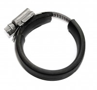
The device of choice these days appears to be the pipe clamp or what the British call the Jubilee clip. The beauty of these clips is that they can be tightened and later if necessary untightened. Seems a little more sound than using up tens of long heavy duty cable ties every time I work on the pole. The clips also make it more practical to dismantle the pole in case of particularly high winds. This would be even easier if pipe clamps with butterfly handles were used in place of the screws.
The clips are available in stainless steel and feature a worm gear driven by a screw thread to adjust the size and pressure of the clip. Spiderbeam offer a set of clips for their Spiderbeam telescopic towers, 11 for the 12m pole. They are sold along with sections of rubber to be used underneath the metal band of the clip to protect the pole.
I have read elsewhere a recommendation to insert the metal band inside a piece of heat shrink for extra protection.
For me though recently, the main question about these clips has been where precisely should they be installed on the pole.
The Spiderbeam company’s advice is clearly to install them not at the overlap but around the thinner upper section to prevent it slipping into the lower section.
Simply put one clamp at the very bottom end of each tube segment and tighten the clamp. Here it will act as a stopper and prevent the tube from sliding downwards into the next bigger tube segment. The rubber padding is made of a thick flat rubber band, protecting the mast against any damage from the clamps.
This advice is quite a surprise to me. It makes sense only if it’s assumed that the pole has been assembled in the normal (?) way of extending the sections and tightening each of them before installing the clips.
On reflection the approach of using the clips more as a stop than a clamp makes more sense. I have always had qualms about compressing the outer tube against the inner tube when they are both rather rigid. The pipe clamps are able to exert quite a deal of compression but that would be unnecessary in the recommended ‘stop’ mode.
My next task is to measure the various diameters of each and every section of my 7m and 10m squid poles from Haverford’s and my 12m Spiderbeam pole, so I can obtain the most appropriate sized pipe clamps for them. TTS Systems, the Australian distributor of Spiderbeam, sells the clamp set for A$44. You can buy direct for 15.55 Euro but postage I think is a lot more.
UPDATE: I purchased the clamp set from TTS Systems. They were easy to assemble. The kit is the set of clamps, a 1.2m length of 3mm thick by 12mm wide rubber strap and black heatshrink to hold the rubber in place.
The completed set of clamps for the 12m Spiderbeam pole
In case you’re wondering – the pipe clamps / jubilee clips sizes for the 11 sections are:
40-60mm x 2, 32-50mm, 30-45mm x 2, 25-40mm, 23-35mm, 20-32mm, 16-27mm, 12-20mm, 10-16mm
As you can see from the photo you need to open the clamps out to install the protective rubber strip and the heatshrink. I suspect the larger, lower clamps are doing the most work.
I installed them on my Spiderbeam pole on a site in the southern highlands. It’s holding up a vertical for 40m, one of a number of antennas to be used in some upcoming contests. Returning after four weeks and strong winds, three of the lower sections had collapsed, so those clamps were tightened. I may have been too tentative/cautious on the initial installation.
Here is the 12m Spiderbeam pole enjoying a clear day in the southern highlands!
The definitive website on how to install the Spiderbeam fibreglass pole clamps is http://www.dj0ip.de/spiderbeam/fiberglass-spiderpole/clamp-sets/ where Rick DJ0IP from Spiderbeam-US explains all – including the advice to use a 7mm nut driver to tighten the clamps.
My main project for at least the last 12 months has been building a solid magnetic loop antenna and its companion automatic loop controller. I’ve been roughly tracking its progress at my magnetic loop antenna project page on this blog.
As usual, life has got in the way, but I want to get back on track and complete the project. To start pumping some RF current through it again, over the weekend I spent a short time playing with the loop on WSPR on 40, 30 & 20m. The tests were too brief but they certainly confirm that the loop is capable of transmitting a signal in spite of the fact the loop is only half a metre above ground and surrounded by metal garden furniture, a steel framed awning and gutters.
I used the WSPR Beacon android app to control my transmitter. There was some discrepancy (tens of Hz) between the actual output frequencies on the app and those shown on WSPRnet. I also found that tuning the loop to each WSPR frequency using the iP30 antenna analyzer was easy and the KX2 gave lower SWR figures.
The brief test became an exercise in understanding theWSPRnet results taking into account propagation and loop orientation which was aligned north-south.
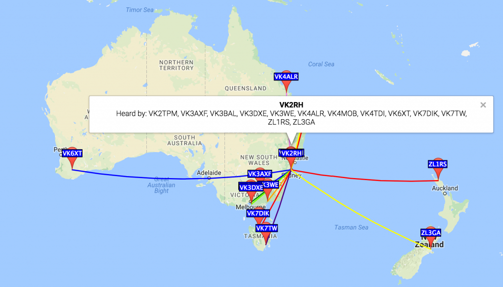
This map view combines all 20 spots of the 1W VK2RH transmissions from grid square QF56oc. The first test was logged at 2017-05-07 01:36 UTC. (I’ve trimmed repeated info from the chart below to improve its fit on the page.)
Time
MHz
SNR
Drift
Reporter
RGrid
km
az
05:24
14.097001
-15
1
VK4ALR
QG56fk
1151
356
05:24
14.097016
-26
0
VK4TDI
QG62lm
733
14
04:48
10.140109
-22
0
VK4TDI
QG62lm
733
14
04:48
10.140094
-23
0
VK7TW
QE37pc
1057
198
04:48
10.140091
-17
0
VK6XT
OF86td
3086
261
04:40
10.140095
-27
0
VK7TW
QE37pc
1057
198
04:40
10.140090
-4
0
VK3WE
QF32se
547
216
04:40
10.140090
-22
0
ZL1RS
RF64vs
2069
101
04:40
10.140092
-15
0
VK6XT
OF86td
3086
261
04:40
10.140091
-16
0
ZL3GA
RE66ho
2130
126
03:18
7.040121
-24
0
VK3BAL
QF22mc
711
230
03:18
7.040134
-7
0
VK3AXF
QF33fn
516
235
03:18
7.040135
-18
0
VK4MOB
QG62ol
734
16
03:18
7.040130
-18
0
VK3DXE
QF21nv
720
228
03:18
7.040128
-12
0
VK2TPM
QF56of
14
0
03:18
7.040129
-14
0
VK7DIK
QE38cu
918
207
01:36
7.040183
-16
-1
VK3AXF
QF33fn
516
235
01:36
7.040177
-16
-1
VK2TPM
QF56of
14
0
01:36
7.040184
-24
-1
VK4MOB
QG62ol
734
16
01:36
7.040179
-21
0
VK3DXE
QF21nv
720
228
40 metres favoured north-south, while 30 metres was literally an all-rounder and 20 metres was too brief. These results probably say more about propagation than the loop, not to mention the heavy lifting done by all the reporter stations extracting my down to -26 or -27 dB signals from the noise! Impressive all round!
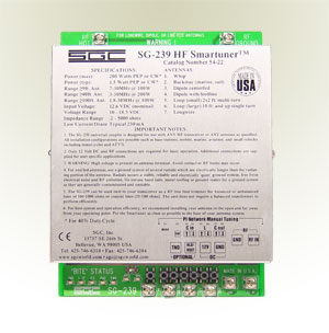
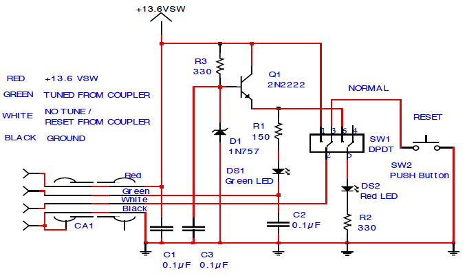
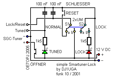
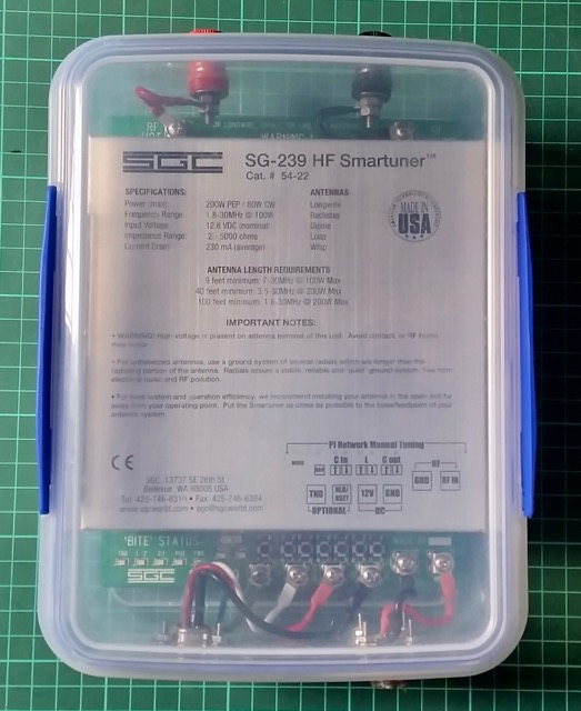
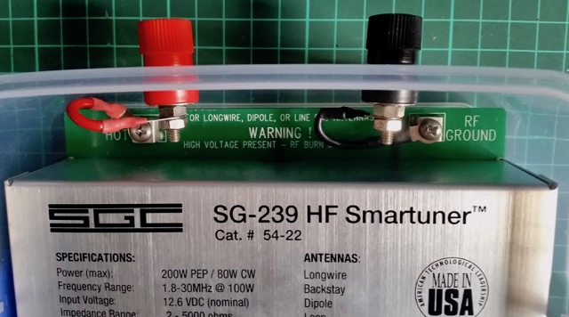
The Smartlock is an accessory for my SGC SG-239 HF Smartuner, and other ATUs they make. It can be bought ready made or built.
SGC SG-239 HF Smartuner witing for a weatherproof enclosure
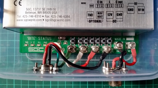
There are indicator LEDs that signal status (TND, l ‘Z’, 2:1, PHZ, FWD, Auto & Man) on the lower section of the PCB of the SG-239 but they are only visible near the unit. As they recommend mounting the unit in a weatherproof container and as close to the feed point as possible, it’s unlikely these will be useable except in testing and servicing.
For reference – here are the indicators and connections on the transceiver end of the SG-239:
B.I.T.E.* Status LED Descriptions – *Built In Test Equipment
TND This LED will light when the tuner has found an acceptable match. It will remain lit until conditions have changed which will cause the tuner to find a different match. (i.e. A new transmit frequency has been detected, or tuner has been reset.)
L ‘Z’ This LED shows the status of the antenna impedance. When lit, the impedance is 50 ohms or less. When off, the impedance is greater than 50 ohms.
2:1 This LED will light when the VSWR is greater than 2:1. It will extinguish when VSWR is less than 2:1.
PHZ This LED indicates the status of the antenna reactance. When lit, reactance is inductive. When off, reactance is capacitive.
FWD This LED indicates the presence or lack of RF power from the radio. When transmitting, the LED will light to indicate RF is being detected. In receive, the LED should be extinguished.
OTHER All LEDs will blink on and off at a rate of 2Hz to indicate the tuner was not able to find a valid match.
The LEDs are very small and quite faint and almost impossible to see on a sunny day.
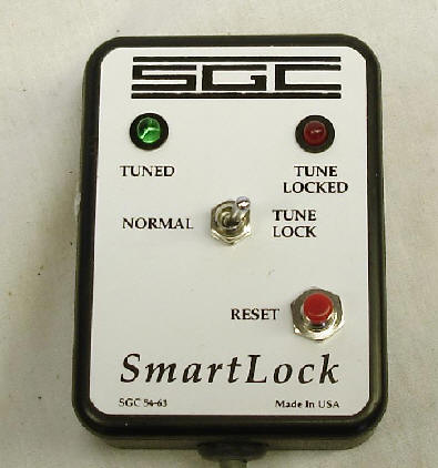
As the ad below indicates the Smartlock provides two controls that can be used remotely from the tuner and close by the radio – allowing the operator to lock or stop the ATU constantly retuning as the load changes and to reset which forces a retune the next time a signal is transmitted.
The Smartlock also indicates if the ATU managed to tune the antenna and if the lock is on. The lock can be invoked when the antenna is to be used for receive or when there are too frequent changes in the physical environment of the antenna such as when mobile and passing trucks or going under bridges….
Installation requires normal coax and a four conductor cable for power and control.
—-
SMARTLOCK, FOR SG-230/237/239 SMARTUNER
$60.00
Catalog #54-63
The SmartLock provides two external controls for the SG-230/237/239 Smartuner. The locking function prevents retuning despite changing antenna loads. The reset function forces the coupler into a retune cycle the next time a signal is transmitted. Tune and lock status is indicated by one green and one red blinking LED. Supplied with 9 feet (2.5 metres) connecting cable. For use with SG-230/237/239 couplers manufactured after July 1, 1993, only.
Its simplicity and the cost of the assembled unit have inspired a number of people to roll their own.
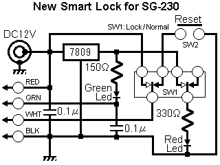
The colour code of the cable to the Smartuner appears to be:
TND = Green,
HLD/RSET = White
+12V = Red
Gnd = Black
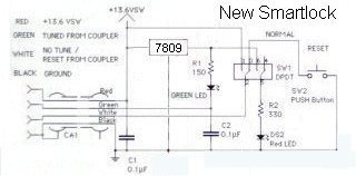
Simplified SmartLock
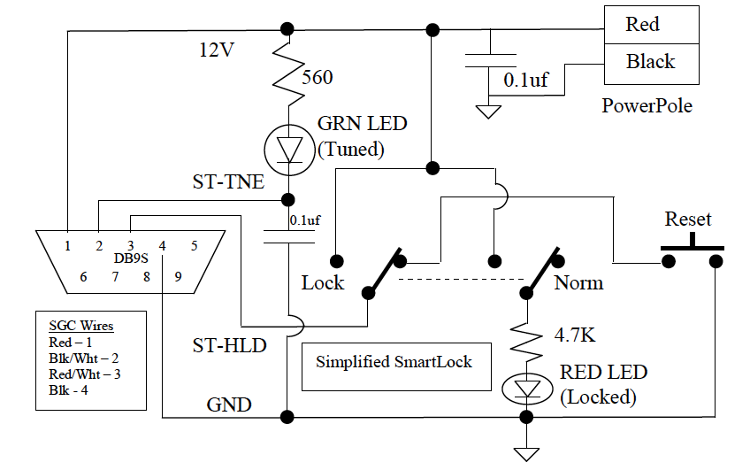
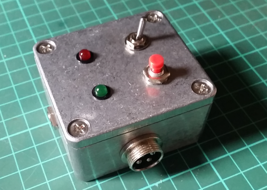
Phil Salas – AD5X – decided to remove the components making up the voltage regulator part of the circuit.
“I wanted to build a SmartLock to use with my SG-239. After studying the SmartLock schematic, I couldn’t figure out why SGC put in the transistor and zener diode. The ST-TNE input on the SG-239 is just a 1.5K resistor to an open collector transistor to ground. So I eliminated Q1, R3, D1 and C3 on the SGC SmartLock schematic. My final circuit is shown below. I used a DB9S connector to interface with the SGC tuner (I attached a DB9P to the tuner interface wires), and a PowerPole interface for 12VDC. This way I could use a standard DB9 extension cable as necessary for interfacing between the tuner and SmartLock. I used ultra-bright LEDs (3000mcd or so) to provide plenty of visibility.”
This uses a tiny PCB available on Italian eBay from a seller who wanted 50 € to send one to Australia!
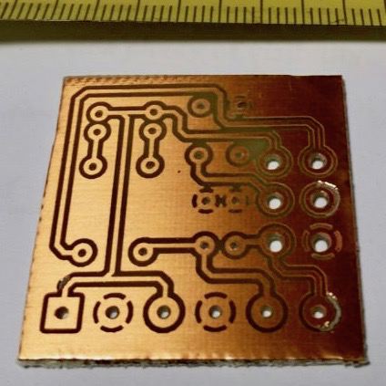
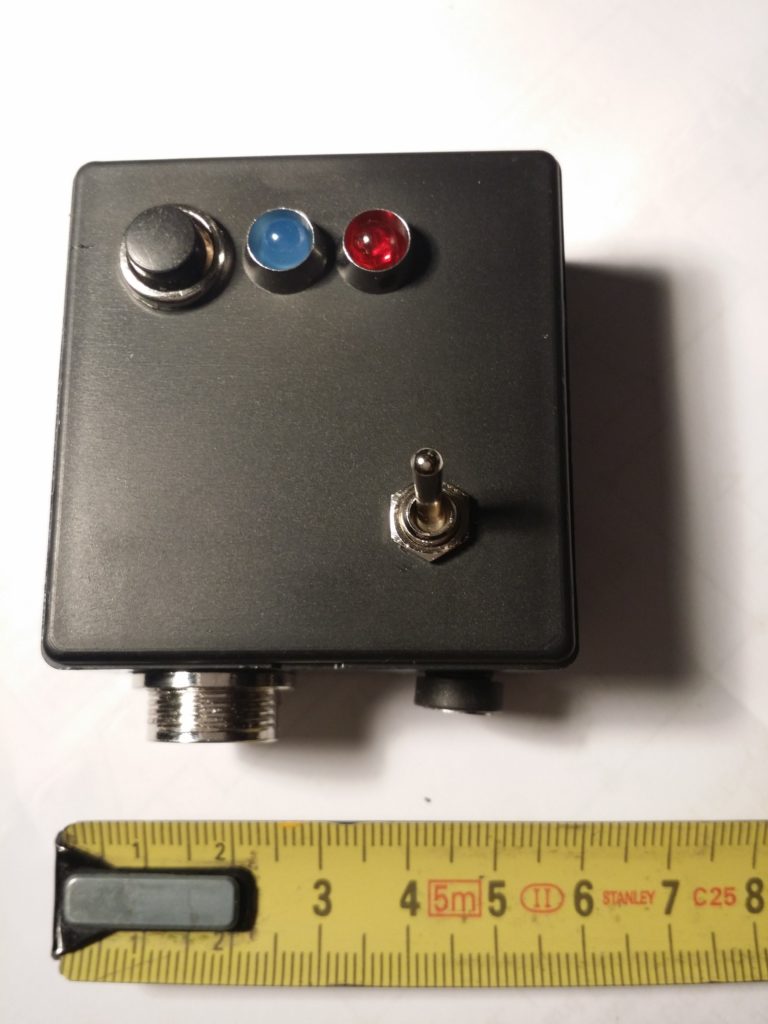
I worked out a way to use a scrap of veroboard to hold the two capacitors and one of the resistors and to manage the wiring between the base and the panel of the enclosure which is probably more efficient and certainly faster. As well I noticed that the PCB seems to be designed for a different kind of DPDT switch where the centre poles are not in the centre!?! So I can add the satisfaction of saving whatever Euros I would have ultimately paid to the greater satisfaction of having nutted out the layout of the veroboard scrap…
Luca used the simplified circuit by Hans Nussbaum DJ1UGA which appears to have in turn have some subsequent input from OE7OPJ (who by the way has a very interesting website at http://www.qth.at/oe7opj/).
L’accordatore automatico SGC-239 indubbiamente è un gran bello strumento. Si collega e funziona ottimamente con qualunque radio (HF) semplicemente utilizzando un cavo coassiale e una fonte d’alimentazione a 12 volts. Non è particolarmente esoso di corrente e anche in utilizzo SOTA non va a gravare sull’autonomia giornaliera. Ne ho trovato uno usato sui soliti canali nazionali ad un prezzo decente e non mi sono fatto scappare l’acquisto. Accorda davvero di tutto gestendo potenze da 1,5 a 200 watt. Ottimo per il mio Yaesu 817, ma altrettanto utile per le “normali” radio munite dei canonici 100 watt. Per poterlo però utilizzare al meglio, si rende necessario l’acquisto di un interfaccia che permette di resettare o bloccare lo stato d’accordo del SGC-239. Tale interfaccia (SMARTLOCK) si trova però in vendita a quasi 100 euro, decisamente troppi per 2 condensatori, 2 resistenze, 2 led e un paio di interruttori. La prima idea è stata quella di prendere lo schema presente sul manuale dell’accordatore e realizzare su basetta forata il circuito. Cosa questa realizzabile, ma che avrebbe dato un idea di “precarietà” a tutta la realizzazione. La scelta a questo punto è ricaduta su un mini circuito stampato realizzato con maestria da Danilo Cramaglia (lo trovate su Ebay come utente Martelloman), che partendo dallo schema elettrico mi ha consegnato quanto riportato in foto:
The SGC-239 automatic tuner is undoubtedly a very nice tool. It connects and works well with any radio (HF) simply by using a coaxial cable, and a power source to 12 volts. It is not particularly power hungry and even practical to use on a routine SOTA outing. I found one used on the usual national channels at a decent price. It really suits around handling power output from 1.5 to 200 watts. Great for my Yaesu 817, but just as useful for “normal” radio equipped with 100 watt “cannons”.
But in order to make the best use, it is necessary to obtain an interface that allows you to reset or block the status of the SGC-239. This interface (SMARTLOCK), however, is for sale at nearly 100 euro, far too much for 2 capacitors, 2 resistors, 2 LEDs and a pair of switches. The first idea was to use the circuit in the tuner’s manual and build it on perforated board. While this is feasible, it could give an idea of “insecurity” to the whole creation. Instead I chose a mini PCB made with skill by Danilo Cramaglia (Ebay-user Martelloman), which, starting from the wiring diagram handed me what is reported in the picture:
I plan to use this wiring arrangement for the 4 pin plugs, socket and line.
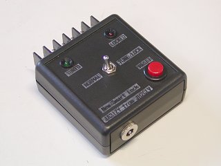
In the hand book to the SGC SG237 Auto Antenna Tuner there is a circuit for an interface they call the SmartLock and it allows some manual control over the AATU and more importantly, it indicates when the tuner has tuned successfully.
The shielded 4 core wire is clamped in the cable tie through a pull through bushing. The case uses a diecast aluminum box TD 5-8-3B (55x30x80) by TAKACHI. The front of the enclosure has the Normal / Lock switch (2-pole, double-throw), the Tuned LED (Green), the Locked LED (Red) and the Reset switch (Make contact). It includes the three-terminal regulator. The bypass capacitors on the circuit diagram are omitted here.
(3) box overview and operation
Once tuning is complete the Tuned LED (Green) glows. If the Normal / Lock switch is pointing to the right, the Lock side, the Lock LED (Red) is lit and fluctuating SWR, etc. does not cause automatic re-tuning.
If the switch is set to the Normal side, normal operating conditions prevail, the SG-239 will automatically start tuning if SWR or the band is changed.
If you press the RESET (red) button, the ATU will re-tune.
For some good ideas about how to protect the SG-239 see http://dg6hd.darc.de/html/sgc-239.html. He uses a large-ish electrical junction box and includes windings on toroids…
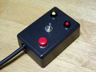
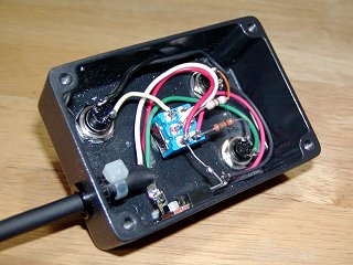
>So here is my effort successfully completed today…
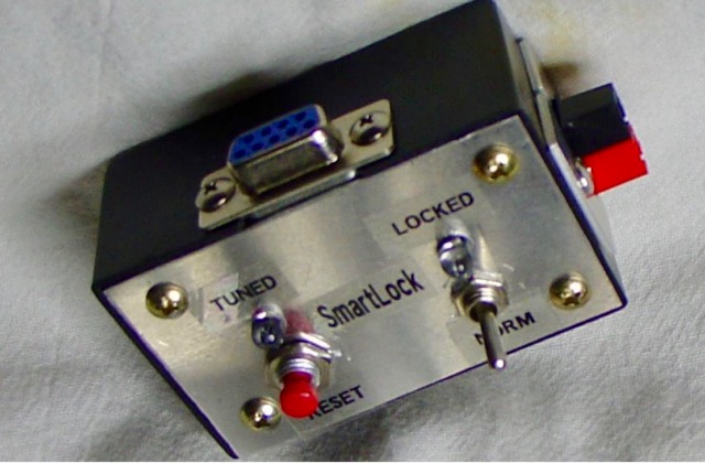
I used the simplified circuit by Hans Nussbaum DJ1UGA and the front panel layout of Phil Salas AD5X. I managed to squeeze everything into a compact package – a small die cast aluminium enclosure 64 x 58 x 35mm which Jaycar sell for $9.95. And that was the main cost. Everything else was on hand.
I’ve yet to label the panel, but the green LED indicates a successful tune, the red LED is on when the switch is in the Locked position, and the push button switch is the reset. I used 4 pin sockets and line plugs to connect to and power the Smartuner. And I used a DC socket to supply 12V power. I had planned to use power poles but decided that would not fit comfortably in this small enclosure.
The ATU is housed in a plastic lunchbox which can be protected by a larger rubber waste paper bin as recommended in the SGC manual.
Great moment this afternoon when the Automatic Loop Controller fired up as it should. Happy days.
The Automatic Loop Controller PCB and display
When I first fired it up, after loading up the Arduino program, all I could see was a dull green glow on the screen. It wasn’t until I remembered a comment from another builder about adjusting the potentiometer on the PCB that controls the LCD contrast.
It was a great relief that my slow and deliberate build – double checking all component values and joints – paid off. Next step is to build the SWR bridge and connect to the stepper motor on the loop.
Also finally managed to make a plate out of perspex to mount my stepper motor on to the supporting bracket on the magnetic loop after much mulling over how to achieve a suitable level of accuracy with my dremel drill press to get the stepper shaft as close to the centre as possible.
The clear perspex mounting plate is sitting above the white plastic mounting bracket with holes for three support struts.
Not too bad for a cut with a straight baby hacksaw. The key tool turned out to be my old school compass which had scribing points fitted which were perfect for marking out the perspex. I figured that these ‘cross hairs’ would help orient and centre the piece and the shaft. After these shots I countersunk the holes. If it looks a little skewiff, that’s probably because it is!
Success – part 2
Also successful today getting this instance of the blog back online using AWS. Another steep but satisfying learning curve about the nitty gritty of DNS management! What’s in a CNAME? you might ask.
Midway through building my version of Loftur Jónasson – TF3LJ / VE2LJX‘s Automatic Loop Controller, I came across Leigh Turner’s impassioned plea to consider this noise bridge antenna tuning design mentioned on page 32 of the “Overview”. As a concluding note VK5KLT states that he considers “The perceived need for a slick and salubrious auto-controller for properly tuning an MLA is oftentimes overrated and exaggerated, IMHO”.
He argued that elaborate microcontroller aided automatic loop tuning circuits are unnecessary and people should consider using this more covert and considerate approach. I think the bridge could be an excellent idea and a simpler way of staying in tune as you change frequency for all sorts of antennas. For a magnetic loop, it still requires a way to remotely adjust the tuning capacitor.
“The circuit goes inline between the rig and the antenna and sends a gated broadband noise signal to the antenna using a directional coupler and a noise bridge. You just listen on the desired operating frequency and watch your RX S-meter for a sharp dip whilst adjusting the loop tuning capacitor.
You simply remotely tune the loop with the aid of the receiver S-meter while you are on the wanted frequency without keying up and TX power output. This makes tuning a breeze without having to move off frequency and have the TX put out any RF power.”
VK5KLT mentioned the MFJ-212 Matchmaker that uses this same approach (and which is still on the MFJ catalog at US$99.95) and also referenced ZL3KB’s April 2001 RadCom article (pp17-21) as an easy and more economical way to replicate the same functionality.
“The distinguishing merit of the novel gated coupler/noise bridge loop tuning method is it’s completely passive and covert in operation; you don’t transmit any TX power whatsoever to attain an optimal loop tune setting. The technique makes for fast, QRM free, safe and easy QSY shifts and netting a frequency.” Leigh Turner adds that it’s even simpler if you use a pan adaptor or a modern SDR receiver as you can see the sharp null on the screen of the band scope display.
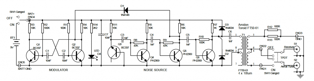
Kelvin Barnsdale ZL3KB’s RadCom article describes building and using the wide band noise bridge as a silent antenna tuning indicator. These four pages include circuit, PCB design and layout and full details of BOM and balun/transformer construction.
On 14 May 2001 ZL3KB published a 4-page follow-up pdf document “Instructions for Antenna tuning Noise Bridge” with info supplementary to the RadCom article about construction and operation. This article has an updated circuit and parts layout and refers to an issue B of the PCB. The new board includes places for the LED and dropping resistor R14, and pads for the two 100Ω load resistors and the two diodes D2 & D3.
This is the updated circuit with some updated values.
This indicates parts placement with the updated PCB.
Here is the foil side of the updated PCB
I contacted Kelvin Barnsdale and was lucky enough to obtain the PCB above.
I spent the pleasant sunny part of the final day of autumn testing a vertical antenna for 80 metres using Buddipole parts for home.
The back garden space here is barely 4 metres by 4 metres and for the moment the chimney is out of reach. While I have dreams of a magnetic loop for 80m, the vertical is more in reach now.
Plan for 80m vertical made from Buddipole components
I installed a counterpoise wire a few feet shy of 66 feet length hidden on a timber fence that runs down the side of the property. The idea is to connect a short fly lead to connect the hidden counterpoise when the antenna is deployed and then disconnect when it’s all packed away. Buddipole components don’t lend themselves to permanent installations. The counterpoise doesn’t follow the recommended dog leg arrangement and is higher off the ground than the 2 feet suggested.
The purpose yesterday was to establish how speedily the antenna could be assembled and adjusted for a frequency of interest such as a net.
Here’s a list of the items used along with the counterpoise:
9′ telescopic whip 2 x 22 inch antenna arms low band coil + clip VersaTee Buddipole short mast Buddipole tripod Balun
I was surprised how easily it all went together. The adjustment wasn’t as fiddly as I expected such a short antenna for this band would be, and it appeared to give a usable bandwidth.
The Buddipole Low Band coil showing the coil tap for 80m
Assembly was straightforward. Set up the tripod and mast with only bottom two sections telescoped out. Attach the Versatee horizontally to the top of the mast. Connect the Low Band coil. Leave the red fly lead loose for the moment. Attach two 22 inch antenna arms to a long whip antenna fully extended. Then carefully attach that assembly to the top of the Versatee. I also connected a 1:1 balun between the Versatee and the iP30 SWR Analyser.
The next step is to simply drag the fly lead across the coil turns to identify the best spot to tap the coil. Background noise level rises as you get in the zone. I used the iP30 SWR analyser to narrow it down to a spot 16 turns up from the base of the coil.
This means I was shorting out the bottom 16 turns of the coil. The adjustment is too coarse on a turn by turn basis. You appreciate the value of being able to tap at 1/8 of a turn increments. (The coil is on an octagonal former.)
It took me a few measurements to realise that as I progressed left (from my point of view) I was decreasing the amount shorted out and hence increasing the loading inductance and so lowering the resonant frequency. It’s actually more confusing reading that sentence than understanding it in practice!
My target frequency was 3535kHz and this is a chart of the SWR readings I had when the coil tap was set at what I calculate to be 15 3/4 turns up from the base of the coil.
frequency
SWR
frequency
SWR
3505
1.8:1
3550
1.1
3510
1.6
3555
1.1
3515
1.4
3560
1.1
3520
1.3
3565
1.2
3525
1.2
3570
1.3
3530
1.1
3575
1.4
3535
1.0
3580
1.5
3540
1.0
3585
1.6
3545
1.1
3590
1.8
The magic spot for my 80m vertical
The 1.0:1 bandwidth was 10 kHz while at 1.5:1 it was in excess of 65 kHz.
From readings at the other possible coil tap points my guess is that at this frequency range each face of the coil moves the resonant frequency by about 4 kHz. One thing to be aware of with the Buddipole hardware is not to accidentally short out adjacent turns of the coil with the coil clip. It’s hard to do but I managed and it will throw your readings.
Next step of course is to make some contacts or at least activate the antenna on WSPR or JT65 to get an idea of whether the signal gets over the fence.
From checking the chart on page 146 of the ‘Buddipole in the Field’ book by B. Scott Andersen, NE1RD, I estimate that my shorting tap at about 16 turns from the base means I’m using about 39-40 uH of loading to achieve resonance at 80m. So that’s a starting point if I wanted to build a more permanent and cheaper vertical installation.