Well, the replacement stepper controller chips arrived early this morning. Didn’t take too long to replace them and connect everything up for a test.
The good news is that after a slight adjustment of VR2 the stepper appeared to be controlled by the rotary encoder. It made the right noises.
Try as I may, I wasn’t able to carry out the initial setup procedure as outlined by Loftur. I couldn’t find a peak in the noise.
After applying a portable SWR analyser directly to the loop when I thought I was at the lowest frequency point the loop would tune, I discovered there was a dip around 23 MHz! I was nearer the other extreme of what I think this loop’s range should be. So I’m thinking I may have the stepper motors wired wrongly with the result that the stepper goes in the opposite direction to what the controller thinks it should be.
After switching one pair of wires at the controller end, the stepper made a terrible noise as it hit the end of the capacitor’s travel. Checking it tentatively it didn’t seem to distinguish between clockwise and counterclockwise movement of the encoder. Whatever you did, the stepper turned in the same direction.
Time for further closer inspection of the wiring around the newly re-oriented common mode chokes and their associated bypass capacitors. This kind of behaviour may have something to do with a missing or failed connection in this part of the circuit.
Stepper only appears to turn CCW which turns the VVC CW. I’m now hoping the glitch is pretty obvious in this part of the board or associated wiring.
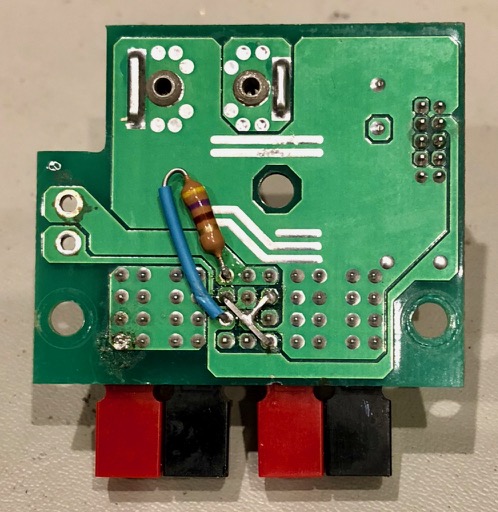
Finally found some time to re-orientate the two transformers. I decided to remove the eight bypass 10nF capacitors to give my soldering iron more wriggle room to remove the transformers. The solder on the transformer pads needed some encouragement – in the form of more molten solder – to loosen up. This allowed me to use solder wick to take away most of what was holding them in place. The corners of the transformer are pretty fragile and would not tolerate much heat. Wasn’t too hard to lift them. Much more complicated was cleaning up the holes where the eight capacitors had been. I managed to destroy one of the pads. Decided to stop destroying the PCB and to re-install the bypass capacitors on the other side of the board.
I was actually able to use most of the capacitors I had removed and checked every connection a couple of times at least, especially a couple of the tiny pads for the caps that are near the larger choke pads.
Soldered the transformers back in properly this time, again checking every step over and over again.
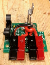
After re-orienting the common mode chokes……and replacing the caps on bottom of the PCB to avoid damaging fragile pads.
Taking a few deep breaths now and having a break before reassembling the whole device and connecting it to the radio and the loop for the moment of truth and to find out if the A4975 stepper driver ICs can come back to life after having both their two outputs accidentally connected together! Normally they are connected across one of the stepper motor windings.
——
Well, because there is still no response from the stepper motor, the answer, unfortunately, is no, they probably need replacement. At least this time they’re not red hot. I have a pair of A4975 chips due to arrive sometime on Monday. Essentially $4.90 a pop, no shipping charge.
And reading the datasheet on the A4975 I see on page 10 mention of the thermal protection circuitry that shuts off the output transistors when the junction temperature reaches +165 degrees C. “This is intended only to protect the device from failures due to excessive junction temperatures and should not imply that output short circuits are permitted.” And I reckon the tiny choke winding is close enough to a short circuit.
At least we are still at three out of four. Looking forward to being able to control the stepper to tune the vacuum variable capacitor and calibrating the controller, and perhaps opening myself up to a new level of complications. At least the well-commented code should be a smart guide.
In the meantime – getting way ahead of myself now – I’m thinking about drilling two holes in the loop to take the stepper wiring, possibly via a length of CAT 5 cable. People seem to think the twisted pairs work well with stepper windings. Not sure what type of connector to use in VVC part and lower down alongside the feed loop SO-237.
I also need to get a couple of plastic pipe ends to fit the PVC tube cover Henrik gave me to weatherproof the stepper and the tuning capacitor.
Then I need to think about a rotator and maybe a tripod roof mounting. And a way of remotely controlling the rotator. Anthony K3NG most probably.
At least it looks like it might be ready to take away to Tooraweenah for a field test in March!!!
Maybe my mistake has been not to refer more directly to the actual code. Over the last 24 hours I have been steadily working through the last two years of email conversations. Loftur keeps the group informed of each new version of the firmware and the newly added features. Sometimes he jumps the gun, but then releases a newer version shortly afterwards.
Well, well well! I think I have discovered why the final part of the loop controller is not working and perhaps why the A4975 stepper motor driver ICs are running so hot. I have just been doing some continuity testing working back from the stepper motor connector, K1 and noticed that there is continuity between C11 and C12 and also between C15 and C16, and there is no continuity between the legs of say C16 and C14 connected T2 etc, all of which implies that I have oriented the common mode chokes, T1 and T2 exactly 90 degrees out from where they should be – I think and I hope… They are both surface mount with four points of contact(!!!!), so there might be some interesting re-working to be done. I actually have one spare if I bugger one up. Also I may need to replace the eight 10nF ceramic bypass caps nearby. But this is progress of a kind.
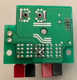
Loop Controller PCB before ‘Aha!’ moment
I wonder what made me install them this way. Surely not simply the orientation of the writing on the package!?!?!?, or the oblong shaped pads on the PCB?!?!?!?! Two visual cues to be misled by!
I suppose I should be optimistic about the transformers being okay if they still show continuity… There’s a big lesson here about using the schematic during the construction and not simply populating the board. And maybe even being curious enough to actually turn the component over to see its magic revealed and be inspired to orient it correctly.
The exterior of the common mode choke with two 51uH windingsInside the common mode choke clearly showing the two 51uH windings
And now of course when I look back to page 8 of the BOM and building instructions I can clearly see the correct orientation of the transformers. Oh me oh my!
And I have just noticed during my rapid review of the emails on the Loop Controller list that on 8 May last year, while advising someone about testing the sense of the stepper winding connections, Loftur dropped this comment, “Also, have a careful look at the circuitry around the A4975 stepper controllers. One fairly common mistake is to mount a common mode choke incorrectly.” I’ll say!
After a long break I have finally got back to completing the Magnetic Loop Controller designed by Loftur Jonasson that I started almost two years ago now. I am using his original PCB version from June 2014 which indicates how long I have been intending to build this device!
I noticed a small SWR board kit based on the kitsandparts kit offered via the Loop Controller list by Frederik ON5IA.
I ordered a couple, but while I was waiting I checked where I had got up to with my original build.
I completed my original SWR bridge board based on the kit from kitsandparts.com. I worked out I could use the same larger gauge bus wire (as used for the single turn in each ToroidCalc1 transformer) to securely and rigidly mount the SWR board to the inside of the BNC sockets. I discovered later that one of the joints to a BNC centre was intermittent, ie not actually soldered!
With the Controller apparently complete, I connected a 4-pin socket to the four wires coming from the stepper motor on the loop and attached the stepper to the VVC with the shaft couplers. I also spent quite a bit of time confirming the correct way to connect the main PCB to the SWR board, to the serial port, to the Stepper motor as well as all the other connectors and controls mounted on the front and back panels of the enclosure.
While the Teensy appears to be working as expected there was no apparent connection with the radio or the loop!!! So far the score is just one out of maybe four! (I suppose my four targets are 1. Teensy controller, 2. Serial connection with the radio, 3. Connection to the Stepper motor and 4. SWR Autotune.)
I did notice scratchy noise due to the dodgy non-joint on one of the BNC sockets. Also the Controller would occasionally just stop and reboot, especially if the enclosure was tilted slightly!
I checked continuity of the earth/-ve line. Seemed intermittent. Noticed I had used nylon stand-offs to mount the PCB. But there was a connection to the metal enclosure between the PCB ground plane via the heatsink tab of the 5 volt regulator. Decided to install metal stand offs. Needed added height of one washer to match original height for the USB socket to match the hole in the rear panel. Also confirmed that the -ve connected directly to the enclosure via the power socket mount.
Properly soldering the antenna lead eliminated the scratchy noise from the radio.
I had last installed firmware version 3.04. I updated the Arduino IDE and re-installed the Teensyduino libraries and then installed the latest version 3.08 of the Loop Controller firmware. No actual difference with connection to radio or loop.
Reading over the last couple of years of conversations on the Loop Controller Yahoo group I came across one post where someone had experienced problems connecting to their KX3. Loftur replied with a check about the way the TXD and RXD is connected to the serial lead. Mine was wired opposite to his description, as I may have confused the order on the serial header and the serial socket. Flipped the TXD and RXD connections and immediately I was able to see the frequency readout on the LCD update after a change on the KX3. Satisfying! A review of the schematic confirmed I had misread it earlier.
This was with the Elecraft K3 Auto setting on the Controller. The controller responds to changes of frequency on the KX3 but only after there is a change. And the update of the information in the frequency display feels a little laggy and as if the update periods are longish. Switching over to the polling method Elecraft K3 Poll the update is much faster and smoother. It also recognises band changes before a change in frequency. (Perhaps I need to change the KX3 setting for AutoInf back to its default). I am using a standard stereo patch cable between the serial port on the controller and the Acc1 socket on the KX3.
One step at a time! Of my four targets then, it looks like we may have achieved two!!! Now just SWR & Stepper to go.
I suppose I should be able to test the SWR board. I have a dummy load connected to the controller ANT BNC. Perhaps I could even calibrate the Power and SWR???? I have checked the ML.h file in the firmware package and read the section in the BOM and Building Instructions pdf (page 13) about the settings to enable the Power/SWR and Autotune options. #define PSWR_AUTOTUNE had been set to 0, so I set it to 1 and verified the program and re-programmed the Teensy. All pretty speedy. And it works, but because frequency ranges have not been set yet it seems to read most frequencies as out of range.
Definitely making some significant progress today!!!
Now to attack the issue with the lack of connection between the controller and the stepper motor.
I examined the solder joints of the two common mode chokes and tested them both for connection and continuity. I have also noticed that the two stepper driver chips are running very hot, way too hot to keep your finger on them for more than a touch. Also there’s probably a static discharge risk there too. Given their cost is only about $7 for these two ICs, it might be worthwhile replacing them, while taking proper antistatic precautions. It would be good if I could discover any other reason/s there is no linkage to the stepper and more importantly why they get so hot so quickly. I hooked up another NEMA 17 stepper motor directly to the board and there was again no movement, but the chips immediately heated up. With the stepper disconnected the chips still heat up.
Time to read more of the manual. That’s the only thing lacking here – a comprehensive manual pitched at dummies like me. I suspect a lot of the wisdom about using this device is waiting to be discovered in the email discussion group. I am slowly working my way backwards over the last almost 2 years I have been subscribed to the list and so far, I’m up to conversation #214 of 265 conversations, that is I have 214 to go! It would be great if you search the conversations directly from the group page… must see why I can’t do that…
Well I have now printed a label for the power connector on the U3S enclosure saying 5V, but it’s a little too late for an assortment of components that inadvertently were subjected to not just 12V but closer to 14V! Yikes.
From consulting the FAQ on the QRP-Labs site at https://www.qrp-labs.com/faq.html I have learnt that I’m am by no means the first to commit this blunder! In fact – as the FAQ on this topic reveals – so many have trod this well-worn path that there’s a pretty good understanding of what needs to be repaired and what probably survived the onslaught of unwanted volts.
Net result as I understand it is:
the main processor, a 28 DIP ATmega328 chip is definitely fried! I do have the option to program a blank one or order one already programmed from QRP-Labs.
The LCD display has been zapped.
The relay on the main Ultimate 3S board has most likely been burnt out as well by the higher voltage.
It’s supposed to be unlikely that the Si5351A Synth Module has been damaged.
On the QLG1 GPS unit it’s probable that the 74ACT08 level converter chip has been destroyed by the high voltage because of the way the LED indicators are behaving when power is applied. Yellow is not pulsing once a second as it should…
This is such an unrare event that QRP Labs have created a product especially for people like me – the QCU QRP labs control unit which components most likely to need replacement after applying the wrong voltage! It includes the 16 x 2 LCD module, 20MHz crystal, BS170 transistor, buttons, resistors, capacitors, hardware and all connectors (4-way sockets, 10-way sockets, 16-way plug/socket for LCD) that are used in the Ultimate 3S kit.
Last night I watched two more episodes of The Get Down on Netflix with my daughter. About 6 minutes into episode 3 of the first season where members of I think the Notorious gang visit Grandmaster Flash to show him the bootleg cassette, you see Flash sitting at a desk with a fat old 2 or maybe even 5-watt resistor and a multimeter. I think it’s a 2.7k ohm value(!).
In the background, there are some signal generators and a big Tektronics oscilloscope. If you visit https://auction.screenbid.com/view-auctions/catalog/id/83/lot/56599/ you can see the actual prop currently being auctioned off. It’s a Tektronics 545A which was made between 1959-64.
Grandmaster Flash’s Tinkering Machine according to the site auctioning props from ‘The Get Down’.
The Smithsonian Institution has one of his actual turntables – a Technics SL-1200 MK2 model.
The Technics turntable used by Grandmaster Flash aka Joseph Saddler
The description mentions
“Grandmaster Flash (Joseph Saddler), was born in Barbados in 1958. Growing up in the Bronx, he was influenced by his father’s massive record collection. As a teenager, Grandmaster Flash first experimented with DJ equipment and became involved in the New York DJ scene while attending daytime technical school courses in electronics. The innovations and techniques developed by Grandmaster Flash established him as one of the pioneers of hip-hop and deejaying.”
An electronics geek with scant funds, Flash constructed a stereo system using parts scavenged from scrapyards and discarded cars and asked the girls he dated if their parents had any records they didn’t want.
This makes my walking a wheelbarrow around my 1960s middle-class neighbourhood as a 13-year-old gathering old discarded radios during council clean-ups quite tame, compared to the virtual war zone of the late 70s South Bronx.
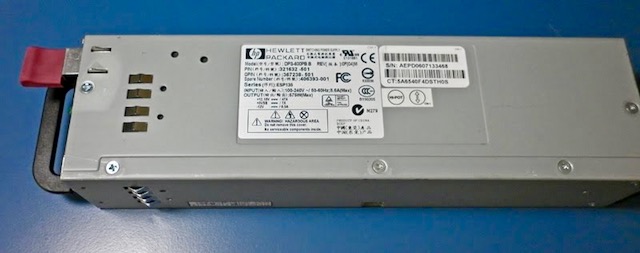
It’s some time since I purchased an HPS 600PB PSU 12V 47A power supply for about $25 from ARNSW. Seeing one in action at our recent club contest station inspired me to dust it off and put it to work.
The HP server power supply popular with hams and radio control fans
These power supplies were designed to be hot-swappable and installed in pairs in racks of HP ProLiant DL380 G4 Rack Servers.
They enjoy a solid reputation for reliability and while designed to deliver 12 volts can reportedly be tweaked to deliver a higher voltage a little closer to ham radio norms, and still deliver high current. The one I saw in action during the recent CQ WW SSB contest was also RF quiet and was comfortable feeding a 100W transceiver for 48 hours straight.
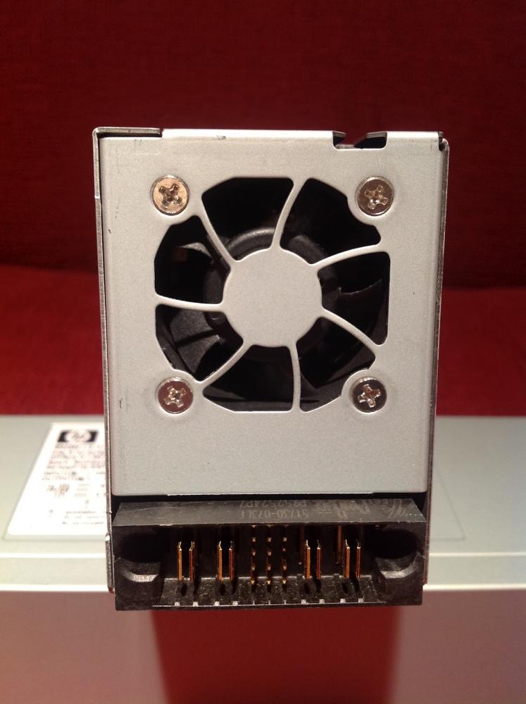
At one end the power supplies are fitted with a regular IEC power socket. At the other end, there is the hot-swap connector.
The business end of the power supplya close-up of the hot-swap connector
IMPORTANT NOTICE: This article is not intended as a guide, it is merely a record of what I have done, for me to refer to when I need to. You must take every precaution when working on this device. The voltages are lethal and you need to be confident in your workshop and soldering skills.
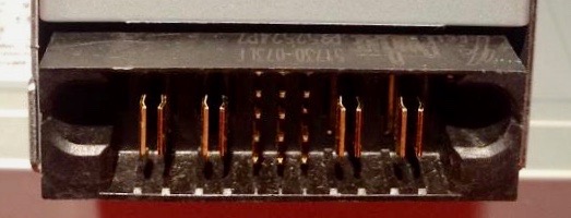
The key information is that the left-hand pair of large blade connectors are both connected to each other and negative/ground and the right-hand pair are both connected to each other and 12 volts positive.
Between these two pairs of blade contacts are 12 protruding pins in four rows of three. Counting from the top and left to right, you can see in the photo that pin number 6 is shorter than the others.
If you simply plug in an IEC power cord into the unit nothing will happen. You have to connect some of the pins together to start the power supply.
I figured the safest and most reliable way to do this – to check that the power supply is working okay – would be to use a pair of 3 x 2 Dupont female pin connector blocks.
Again counting from the top left, I mounted female pins in the blocks so that pins 6, 8 and 10 would be connected together. Pin 8 is connected to the ground. And pin 10 is PSON. I’ve read that some people have installed an on-off switch between pin 10 and pin 6.
I had also read about a common modification to control the fan speed. Unmodified – with pins 6 and 10 connected to pin 8 – the fan runs at maximum and so could be considered noisy. Connecting pin 4 to pin 8 slows the fan down, but it is still able to increase its speed when required.
I tried without this mod – to hear how loud the fan actually was – and with the modification – to see what difference it made. This 5 MB 8-second long mp4 clip shows the clear difference in fan noise, before and after grounding pin 4.
The sound level difference is significant enough to leave pin 4 connected to pin 8 ground.
The next stage of my adaptation was to fit Anderson Power Poles in place of the hot-swap connector. People have soldered large terminals to the blade connectors, but I wanted something safer and easier to connect with the rest of my radio gear.
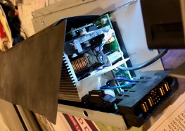
It’s pretty straightforward dismantling the power supply. Be careful to ensure the supply has been disconnected and powered down.
Basically remove every screw you see, except the four holding the small fan. You’ll see three slots inviting you to slide one of the panels along, but you can’t until you break the bond between the aluminium panel and the black plastic insulation material attached to the panel by double-sided adhesive tape. It will come free – and can be helped along with a knife blade to break the adhesion.
Top centre you can see the connector for the fan. This can be left connected throughout. In the centre, you can see I have already removed the screws on the two metal flanges connecting to the main board, and on the bottom, you can see the hot-swap connector.
Remove the screws holding the two metal flanges mounted on the board to pillars on the main board. These carry the voltage through to the blade connectors.
I released the ribbon cable from its clip.
There are two more screws holding the small printed circuit board with the hot-swap connector to the enclosure. Remove these. Also use a nut driver to remove the nut in the centre of the board attaching it to the enclosure.
I unsoldered the blue and purple wires – after taking a quick photo of how they were wired. (Purple to +5V)
Now I could remove the hot-swap board completely from the power supply.
The next step is to remove the connector without damaging the printed circuit board. The amount of metal in the connectors and on the traces of the printed circuit board means that unsoldering is not practical. I have heard of people using a heat gun to dislodge the connector. But again you need to be careful not to destroy the board.
I opted for a more direct approach – slowly using a precision model hacksaw to remove sections of the connector. It was slow and messy but I was left with a clean and largely undamaged board with ample room to install two pairs of Anderson Power Poles.
I trimmed and tidied up the board where the 12 pins were connected. I unsoldered the holes into which I planned to install jumpers – that is 4, 6, 8 and 10. I also cleaned up holes 3 and 9 with plans to install a resistor to effect a rise in the output voltage.
I actually used the square profile wire used for the pins to make first a small link between pins 4 and 8, and then soldered a longer link above it joining pins 6 and 10 to this lower link. I presume it’s important that each of these holes retain a short conductor to ensure continuity between traces on both sides of the printed circuit board.
The bottom of the printed circuit board where the links joining pins 4 and 8, and then 6 and 10 are visible. Pins 3 and 9 are clean and ready for voltage adjusting resistor.
I’ve been advised that the simplest way to install the APPs is to superglue them to the top of the board. But first I cut and prepared some short lengths of heavy wire to connect the power poles to the metal flanges, making sure that the centre hole where the nut came from is not obstructed.
Anderson Power Poles connected and positioned for wiring to clear the central mounting hole.
And that is as far as I have progressed. I’m unsure what value resistance to connect between pins 3 and 9. While it’s possible to raise the voltage up to 13.8 it’s not practical as the overvoltage protection disables the supply under heavy load. I’m happy to settle for a voltage just over 13 volts. It may involve trial and error to see what the best value is. I plan to start with a 470Ω resistor.
Studying the photo of the bottom of the PCB above has revealed an alternative place to mount the resistor that won’t require soldering access to the top of the board beneath the power poles – which is basically impossible. Instead, I can follow the sizeable PCB traces connected to pins 3 and 9 and scratch convenient points to attach the resistor. I’ll put a wire back into the two holes. Also, the resistor should have heat-shrink insulation to prevent unwanted connections.
My main mistake was not doing this resistor testing when I first set up the supply with the Dupont connectors. It would have been easy then to identify the right resistor value.
UPDATE: I installed a 470Ω resistor, superglued the Power Poles and held them in place with a pair of clamps for a couple of hours while the glue dried. Then I reassembled the power supply – reconnecting the blue and purple wires and the ribbon cable and reattaching the board to the enclosure. I re-used the ends of the original hot-swap socket to be able to use the original screws rather than source shorter ones.
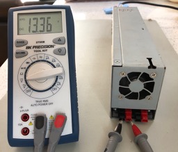
The 470Ω resistor installed to adjust output voltage up from 12.5VMoment of truth – with my power supply 470Ω across pins 6 & 9 changed output voltage to 13.3V
This was a great result. Right in the range I was aiming at.
Since they were invented – apparently by an Australian engineer (see below) – milk crates have been used in many other ways besides holding milk containers.
A milk crate chair by Matt Sutter
Everything from furniture to milk crate versions of the Loch Ness monster.
Milk crate Nessie emerges from Australian backyard swimming pool!
Six interlocking milk crates stacked is 186cm high.
They feel stable but they need a flat level base.
They lend themselves to cable ties to tie together and offer numerous points for guying and attaching halyards.
Not sure how strong they would be at a height of 10 or 12 metres and whether they are structurally strong enough to withstand the forces exerted by guy lines etc. Presumably they would have a high degree of wind loading comparable to a steel lattice tower.
Not sure of the actual plastic material they’re made of – PE extrusion? It would be important to find out how strong it is especially where shackles etc might be connected for guying and attaching pulleys for halyards etc.
If six crates are 1.86m high, 18.6m requires about 60 crates (!) so I guess 9m equals 29 crates in a stack! 10m = 32 crates and 12m is about 40 crates.
It would not be practical to assemble a tower crate by crate from the base up as the upper crates would quickly become unwieldy and too heavy to lift. The same problem would arise with sections of a number of crates at a time. So there would be the same problem of the stresses involved in tilting and lifting any horizontal structure into a vertical position especially at the base pivot point. All crates would need to be tied together on all four sides, top and bottom, so requiring (4n + 4) ties where n is number of crates. I assume the interlocking crates would be solid when tied together.
The crates are bulky and may not be so practical for portable deployment. External dimensions are 36cm x 36 cm and 32cm high so 9 would occupy 108 x 108 x 32cm or 0.37 of a cubic metre so 40 crates for a 12m milk crate tower would occupy about 1.66 cubic metres.
One other downside besides wind loading might be the actual weight of the structure should it collapse. Long-term exposure to UV may also be an issue for a more permanent installation.
Below, a table listing various – mostly unrelated – pros and cons – the biggest one, of course, being that using them in this (or any other way besides storing milk containers) amounts to theft in the eyes of the makers and owners of the crates.
pros
cons
cheap!
long/short term “borrow” required
modular
bulky
requires no machining or preparation beyond cable ties
high wind loading
ready-made solid structure
weight if tower falls
colourful
UV exposure?
Here’s a Sydney Morning Herald report featuring the Australian engineer, Geoff Milton who designed the milk crate for Dairy Farmers and how they designed it with holes big enough for potatoes to fall through to discourage theft. This doesn’t explain why they made their internal dimensions the perfect size for storing vinyl LPs!
Coincidentally these milk crates were made by Nally, the same name as the manufacturer of Nally Radio Towers that shut down in 2015 when the owner passed away.
I finally found some quality time to spend on the QCX to work out why I wasn’t getting any RF output. In my efforts, I committed one of those predictable errors and very unscientifically changed one more factor than I should have. This resulted in a detour that made the search longer, but it did reveal something interesting about the radio.
I had decided I needed to thoroughly check out all the connections in the bandpass filter and the RF amplifier section, even though I had been very careful visually checking and testing continuity at each step of the build. But the fact of the matter was there was no power at the output. At key down, I was getting 0.01 volts. I re-flowed a number of joints on the printed circuit board. Under magnification at some angles, even the neatest solder joint can look like a cold joint.
I also suspected that some of my earlier ham-fisted testing of the radio may have created its own casualties. I was so keen to try out the built-in test equipment, I connected up my probe incorrectly. I was probably tired. I was definitely woken up by the little spark, then the fact that the wire I was holding suddenly went limp and then a puff of magic smoke emerged from behind the LCD panel! I had connected the SCK pin on the programming header instead of the RF pin nearby to the RF output!
From all the discussion on the QRPLabs email group, I guessed that Q6, the MPS2307A had probably been the source of the smoke. The consensus seems to be that they may be underrated. Hans is now shipping a more resilient transistor the MPS751 in its place. I couldn’t source any of these quickly and locally so opted to replace the original with another MPS2307A. After I had removed the transistor I tested it on a nifty component tester which concluded that rather it was actually a pair of resistors rather than a transistor. This seemed to confirm I must be on the right track.
My next mistake was to decide to test the radio using a different voltage to earlier testing. I had read that the recommended range of voltage extends from 7 volts up to 16 (see page 5 of the manual), so I thought I’d use 9 volts. I think, also that the only way to reduce output power is by reducing the voltage. In any case, after I re-connected the radio, I noticed first of all that the sidetone was somehow delayed. If you sent a series of dits at say 15 wpm, you wouldn’t hear anything. And you had to hold the dash to hear it eventually.
I had the dummy load connected to the antenna and tuned a local receiver with no antenna connected to the same frequency and noticed that actual signal was not delayed. That’s interesting! Is there component where the sidetone is generated introducing the delay? I also realised that I was actually getting some RF output which I measured at about 1.3 watts. The voltage was just over 9 volts and the RF voltage across the 50Ω dummy load was about 11 volts. The RF output was good but the delayed sidetone was a bit like talking with a delayed echo in your ears. Between this paragraph and the next, there was a fair amount of head-scratching and further checking.
Then I decided I should see what the RF output is with a more regular voltage like 13.1 volts. I was delighted to see the voltage across the dummy load at 20 volts which neatly converts to 4 watts. And I was even more delighted to hear that the sidetone was back in sync with the key! So the lag appears to have been a result of the lower voltage. I’m not sure what the implications are of this if you want to wind back the wick and transmit at a lower output level. The signal sounded clean – it was just the sidetone that was laggy.
Another thing I learnt during this phase of the troubleshooting was that a good way to remove the remnants of a component like a transistor is to melt some fresh solder on the joint to get the heat to flow more readily to loosen things up. I think I became better at using solder wick as well, with a dab of the flux pen. The printed circuit board stood up to my efforts replacing the transistor and other components like one of the toroid coils when checking the leads. I used a fine pointed iron tip at 370° C.
Everyone says that the overwhelming majority of faults with home constructed electronics kits – at least 90% – are to do with the soldering not being up to scratch. So I figure all the time spent checking solder joints during assembly and afterwards paid off. If you tell yourself how much time you’ll save later, it becomes a more enjoyable part of the whole assembly process.
I also finally managed to upgrade the firmware using the Arduino Uno and Avrdudess application. I had to force it but at long last, the application finally recognised the identity of the microcontroller in the radio. There must be a dodgy connection between the radio and the Arduino.
Now I’m confident it’s working as it should I should make some contacts and then work my way through the manual again to confirm all is as it should be. But I will be much more careful checking any voltages!
There are a number – probably set to grow – of YouTube videos dedicated to the assembly of the QCX.
The most impressive, not just for its length, is the feature film length video by Roberto IZ7VHF. It’s a beautifully filmed love letter to the radio as well as a video record of Roberto’s build. It was recorded in September.
One of the aspects I’ve been surprised and impressed with is the quality of the CW decoding while sending. While playing with the onboard microswitch as a morse key I felt I needed to emphasise the length of the dashes for the encoder to resolve my sending. So I was pleasantly surprised at how well the decoding worked with a straight key and a sideswiper. These keys didn’t seem to impose the same timing expectations as the microswitch – which is odd because I believe they are wired across each other.
In any case, the decoder was able to present a pretty reliable rendition of what I had sent with both keys. Other systems I’m familiar with are only successful with keyer generated CW sent on a paddle. I’ve only seen sideswiper CW decoded by the Begali CW Machine which is a bit more expensive than the QCX but essentially built around a tiny AVR Butterfly.
Decoding in receiving on the QCX sometimes seems to be jeopardised by noise and static, although some quite clear and strong signals occasionally would not be decoded. I need to experiment more to do it justice and check what impact the speed adjustment has because ultimately it all must be using the same microcontroller code to decode the morse, sending or receiving.
One topic on the QRPLabs discussion group is the ideal enclosure for the little radio. The designer Hans G0UPL planned for all controls to be mounted on the small 10 x 8 cm PCB and provided for those who prefer to mount it in a protective enclosure.
As mounted on the PCB the shafts of the AF gain control and the rotary encoder are slightly different lengths and the tiny momentary switches are a long way from any front panel.
Part of the appeal of such a small radio is being able to show it off to friends so in one sense especially for this prospective audience an enclosure denies this pleasure – unless of course its transparent.
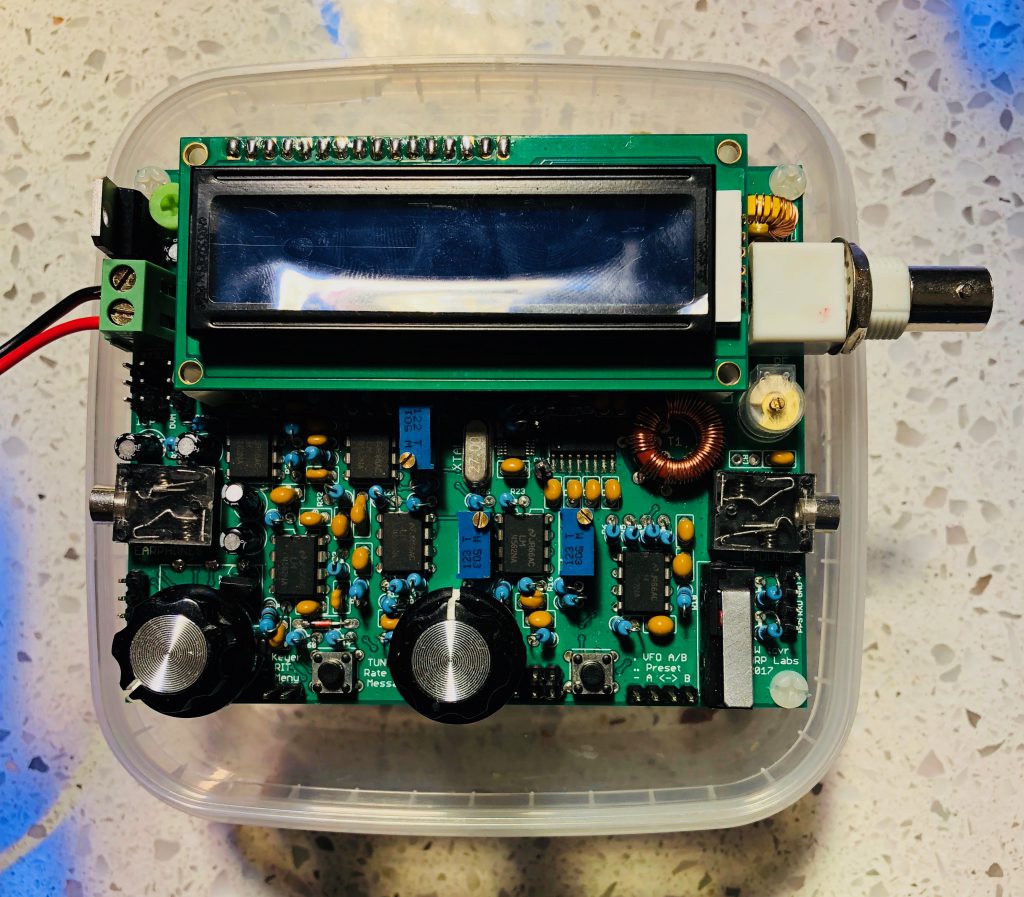
For the moment at least I think I may stumbled on to a neat solution. On the kitchen bench.
A suitably sized plastic container
The price is right and it’s tasty too!
Almost made to measure!
This way I can keep tweaking the radio and store it with a degree of protection. I started out with this 40m version with the pot and encoder connected by headers with a view to finding an enclosure later, but this solution feels a little neater and safer. And there may even be space for a battery.