It’s some time since I purchased an HPS 600PB PSU 12V 47A power supply for about $25 from ARNSW. Seeing one in action at our recent club contest station inspired me to dust it off and put it to work.
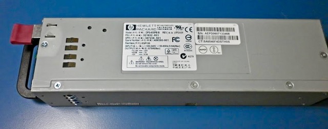
These power supplies were designed to be hot-swappable and installed in pairs in racks of HP ProLiant DL380 G4 Rack Servers.
They enjoy a solid reputation for reliability and while designed to deliver 12 volts can reportedly be tweaked to deliver a higher voltage a little closer to ham radio norms, and still deliver high current. The one I saw in action during the recent CQ WW SSB contest was also RF quiet and was comfortable feeding a 100W transceiver for 48 hours straight.
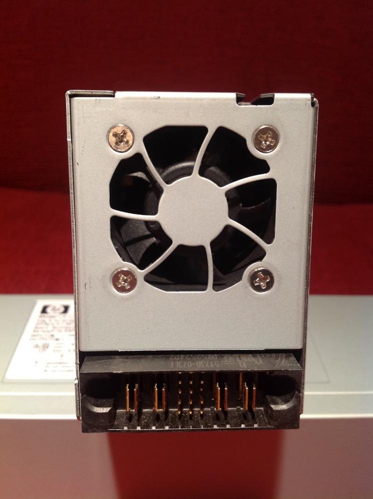
At one end the power supplies are fitted with a regular IEC power socket. At the other end, there is the hot-swap connector.
IMPORTANT NOTICE: This article is not intended as a guide, it is merely a record of what I have done, for me to refer to when I need to. You must take every precaution when working on this device. The voltages are lethal and you need to be confident in your workshop and soldering skills.
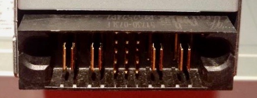
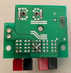
The key information is that the left-hand pair of large blade connectors are both connected to each other and negative/ground and the right-hand pair are both connected to each other and 12 volts positive.
Between these two pairs of blade contacts are 12 protruding pins in four rows of three. Counting from the top and left to right, you can see in the photo that pin number 6 is shorter than the others.
If you simply plug in an IEC power cord into the unit nothing will happen. You have to connect some of the pins together to start the power supply.
I figured the safest and most reliable way to do this – to check that the power supply is working okay – would be to use a pair of 3 x 2 Dupont female pin connector blocks.
Again counting from the top left, I mounted female pins in the blocks so that pins 6, 8 and 10 would be connected together. Pin 8 is connected to the ground. And pin 10 is PSON. I’ve read that some people have installed an on-off switch between pin 10 and pin 6.
I had also read about a common modification to control the fan speed. Unmodified – with pins 6 and 10 connected to pin 8 – the fan runs at maximum and so could be considered noisy. Connecting pin 4 to pin 8 slows the fan down, but it is still able to increase its speed when required.
I tried without this mod – to hear how loud the fan actually was – and with the modification – to see what difference it made. This 5 MB 8-second long mp4 clip shows the clear difference in fan noise, before and after grounding pin 4.
The sound level difference is significant enough to leave pin 4 connected to pin 8 ground.
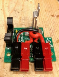
The next stage of my adaptation was to fit Anderson Power Poles in place of the hot-swap connector. People have soldered large terminals to the blade connectors, but I wanted something safer and easier to connect with the rest of my radio gear.
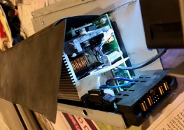
It’s pretty straightforward dismantling the power supply. Be careful to ensure the supply has been disconnected and powered down.
Basically remove every screw you see, except the four holding the small fan. You’ll see three slots inviting you to slide one of the panels along, but you can’t until you break the bond between the aluminium panel and the black plastic insulation material attached to the panel by double-sided adhesive tape. It will come free – and can be helped along with a knife blade to break the adhesion.
Remove the screws holding the two metal flanges mounted on the board to pillars on the main board. These carry the voltage through to the blade connectors.
I released the ribbon cable from its clip.
There are two more screws holding the small printed circuit board with the hot-swap connector to the enclosure. Remove these. Also use a nut driver to remove the nut in the centre of the board attaching it to the enclosure.
I unsoldered the blue and purple wires – after taking a quick photo of how they were wired. (Purple to +5V)
Now I could remove the hot-swap board completely from the power supply.
The next step is to remove the connector without damaging the printed circuit board. The amount of metal in the connectors and on the traces of the printed circuit board means that unsoldering is not practical. I have heard of people using a heat gun to dislodge the connector. But again you need to be careful not to destroy the board.
I opted for a more direct approach – slowly using a precision model hacksaw to remove sections of the connector. It was slow and messy but I was left with a clean and largely undamaged board with ample room to install two pairs of Anderson Power Poles.
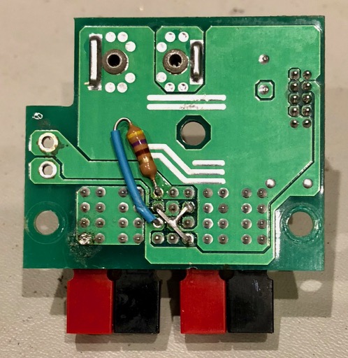
I trimmed and tidied up the board where the 12 pins were connected. I unsoldered the holes into which I planned to install jumpers – that is 4, 6, 8 and 10. I also cleaned up holes 3 and 9 with plans to install a resistor to effect a rise in the output voltage.
I actually used the square profile wire used for the pins to make first a small link between pins 4 and 8, and then soldered a longer link above it joining pins 6 and 10 to this lower link. I presume it’s important that each of these holes retain a short conductor to ensure continuity between traces on both sides of the printed circuit board.
I’ve been advised that the simplest way to install the APPs is to superglue them to the top of the board. But first I cut and prepared some short lengths of heavy wire to connect the power poles to the metal flanges, making sure that the centre hole where the nut came from is not obstructed.
And that is as far as I have progressed. I’m unsure what value resistance to connect between pins 3 and 9. While it’s possible to raise the voltage up to 13.8 it’s not practical as the overvoltage protection disables the supply under heavy load. I’m happy to settle for a voltage just over 13 volts. It may involve trial and error to see what the best value is. I plan to start with a 470Ω resistor.
Studying the photo of the bottom of the PCB above has revealed an alternative place to mount the resistor that won’t require soldering access to the top of the board beneath the power poles – which is basically impossible. Instead, I can follow the sizeable PCB traces connected to pins 3 and 9 and scratch convenient points to attach the resistor. I’ll put a wire back into the two holes. Also, the resistor should have heat-shrink insulation to prevent unwanted connections.
My main mistake was not doing this resistor testing when I first set up the supply with the Dupont connectors. It would have been easy then to identify the right resistor value.
UPDATE: I installed a 470Ω resistor, superglued the Power Poles and held them in place with a pair of clamps for a couple of hours while the glue dried. Then I reassembled the power supply – reconnecting the blue and purple wires and the ribbon cable and reattaching the board to the enclosure. I re-used the ends of the original hot-swap socket to be able to use the original screws rather than source shorter ones.
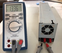
This was a great result. Right in the range I was aiming at.
Leave a Reply