0 Background
I’ve been interested in magnetic loop antennas for some time now. I have read as much as I could find about the design and practicalities of building them. A key reference is Leigh Turner VK5KLT’s comprehensive “Underestimated Magnetic Loop Antenna” version 1.2.
I’ve also used the portable Alexloop and found it very effective. The magnetic loop antenna seems like a potential solution to the problem of having little or no space to erect a normal dipole in a built up inner city location. A key characteristic of magnetic loop antennas is the very narrow bandwidth when tuned, so that if you QSY a few kHz you need to retune the loop. But this makes the antenna very selective and sharp.
Earlier this year I saw a very impressive magnetic loop design being used by a fellow radio club member, Henrik VK2HHS. It was a substantial piece of work being a 1.2m (c 4′) diameter loop of 38mm (1 1/2″) diameter aluminium tubing. It had two solid vertical tear drop shaped flanges at the top that bolt directly to the end flanges of a 200pf vacuum variable capacitor. Henrik had the opposite end of the loop mounted on a bracket sitting in a mount normally used to hold up a squid pole in the sand or soft ground.

I was impressed as much by the clever design of the loop as by the solidity of the build.
This was one of its first outings and it was put to work on 20 metres during a contest while a group from the club were operating over a weekend in the western part of New South Wales.
Talking with Henrik I discovered we were both planning to build the Automatic Loop Controller designed by Loftur Jónasson TF3LJ/VE2LJX. This is essentially a way to use a small arduino controller to control a stepper motor driving the vacuum variable capacitor. With frequency info supplied by the radio the controller is able to automatically keep the loop in tune within the design range.
Over the middle of this year I’ve been slowly gathering the bits I need to build the magnetic loop and the controller.
After obtaining the loop and the other major components, I broke the magnetic loop project down into six parts – arranged here in what I think will be the logical order of the build:
- mounting vacuum variable capacitor to main loop
- mounting main loop to mounting bracket
- making & mounting coupling loop to main loop
- choosing a support for the completed magnetic loop
- mounting stepper motor to vacuum variable capacitor
- weatherproofing the vacuum variable capacitor and the stepper motor
1 Mounting vacuum variable capacitor to main loop
The loop is designed for a type of vacuum variable capacitor with mounting holes at each end. I ordered an EL7.5-200S-333 Vacuum Variable Capacitor, 10-205pf, 7.5kv Peak, Energy Labs from RF Parts. The VVC cost about US$190 and postage to VK was about half that again!
When my capacitor arrived I was shocked to discover that the shaft just seemed to turn freely. I confirmed with a capacitance meter that there was no change. I emailed RF Parts and they asked me to try a number of tests and remedies. When these failed they asked me to return the VVC as it was under warranty. About a week or so later they sent me a replacement capacitor even more protectively packed up than the first one that was working exactly as expected. So I was very relieved and impressed with their service even though I was out of pocket the return postage.

There are six holes at each end threaded for 8-32 UNC.
2 Mounting main loop to mounting bracket
The loop is attached by two suitably sized U bolts with mounting saddles to a bracket with a flat section of stainless steel welded to a tubular section of stainless steel 38mm (1 1/2″) diameter.
3 Making & mounting coupling loop to main loop
I bought a ‘pancake’ roll of 1/4″ copper tubing from Haiton in Lidcombe, NSW. They supply material to refrigeration and air conditioning trades. The 5m roll cost me $19.25.
Based on the universal guideline that the feed loop should be 1/5 the size (radius or diameter) of the main loop I measured 800mm of the tubing. This was easily shaped into the required flat circle. I put each end in turn into a vice (about 10mm) and flattened it in the same plane as the actual loop. I then drilled appropriate size holes into the flattened ends to accommodate the centre pin on tha back of the SO-239 socket and one of the three M3 bolts holding the SO-239 flange.

The SO-239 was mounted on the vertical face of a 3mm thick piece of perspex bent into an L or U shape. The shorter horizontal (base) of the perspex piece was drilled with four 3mm holes to hold two clips I luckily had on hand.
They were bought some time back from Bias Boating supplies. They are called a narrow base tube holder. They are available for different diameter tubing. From their website I deduced mine must have been item no. 4349B – black for 38mm diameter tubing.
This is probably a temporary arrangement but it does look like it could be a solid platform for experimentation regarding the distance of the feed loop from the edge of the main loop etc.
4. Choosing a support for the completed magnetic loop
I decided to use a strong tripod. I noticed that a suitable choice could be the tripod used for a laser level. In the end I discovered that as luck would have it, the Buddipole tripod is designed for a 1 1/2″ diameter mast so I had a perfect fit for the mounting flange.
At this stage it’s possible to test the antenna’s perfomance.

My first tests were to check SWR on different bands. I was delighted to see it get very low on 40m and 30m (1.2:1), but it was not as low on 20m (1.6:1).
My other test was to run WSPR at low power on 20m. I was impressed with the loop’s performance given the proximity to metal clotheslines and roof etc. Spots in VK5, JA, ZL etc. Orientation did not seem to play much of a role. Loop was oriented north-south.
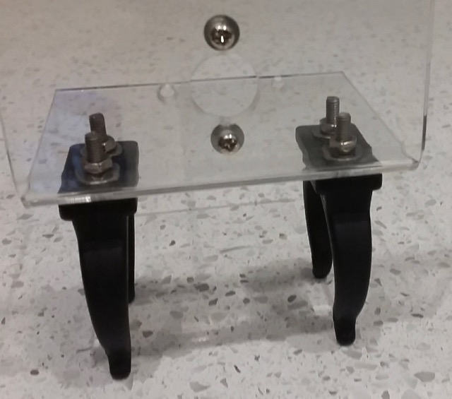
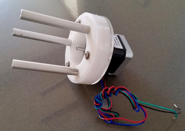
5. mounting stepper motor to vacuum variable capacitor
Henrik’s design uses three 75mm long shafts threaded with 8-32 at each end. I think he sourced his from left over rack unit front handles which he squared off and threaded.
These three rods are used to hold a plastic disc cut and turned from any handy suitable plastic material and drilled to accommodate the three 75mm shafts and the stepper motor.
In mine I used a circular mount intended for a circular bodied stepper and added a perspex disc to act as an adaptor to hold my square shaped stepper in the right position.

The three holes for the bolts to hold the three struts/shafts are counterbored.

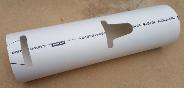
6. Weatherproofing the vacuum variable capacitor and the stepper motor
Henrik’s design includes a length of PVC drainpipe (ext diameter 90mm – int diameter 86mm) with suitable cutaways to enable it to slot over the vacuum variable capacitor and stepper motor assembly. End caps will finish the installation.
to be continued…