Category: QCX

  • QCX – All systems go!

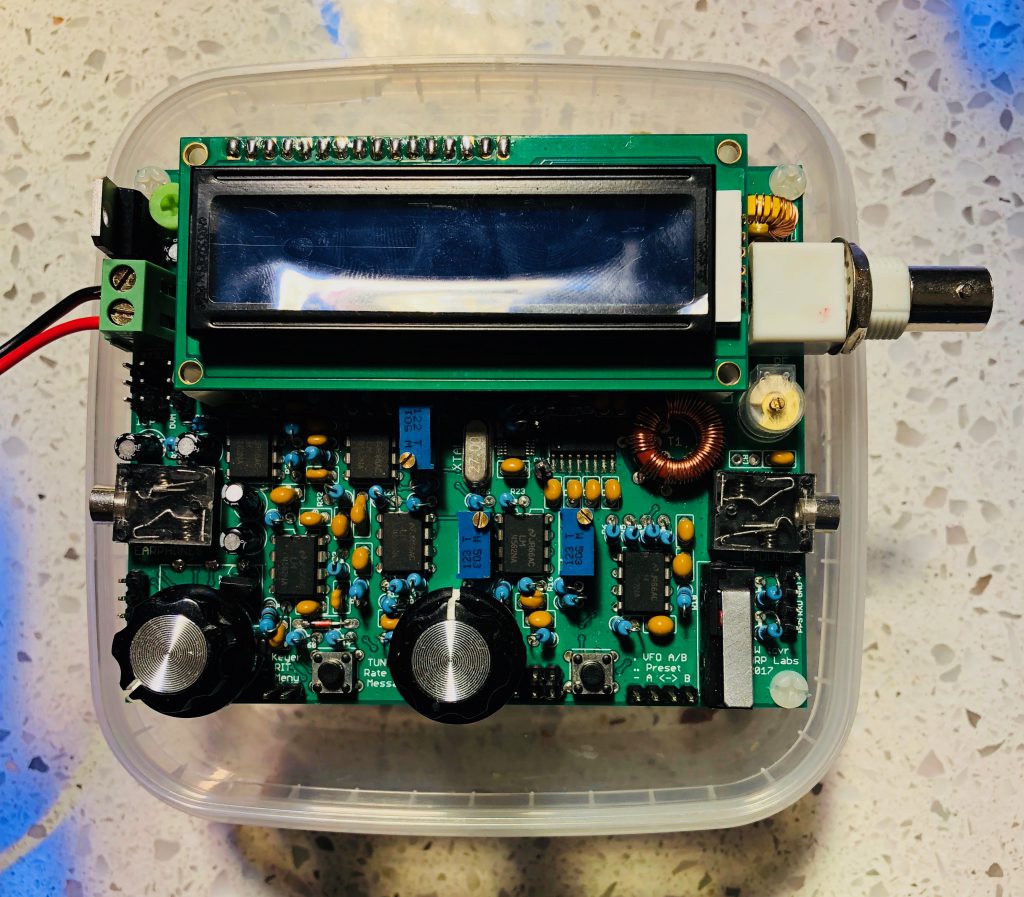
    I finally found some quality time to spend on the QCX to work out why I wasn’t getting any RF output. In my efforts, I committed one of those predictable errors and very unscientifically changed one more factor than I should have. This resulted in a detour that made the search longer, but it did reveal something interesting about the radio.

    I had decided I needed to thoroughly check out all the connections in the bandpass filter and the RF amplifier section, even though I had been very careful visually checking and testing continuity at each step of the build. But the fact of the matter was there was no power at the output. At key down, I was getting 0.01 volts. I re-flowed a number of joints on the printed circuit board. Under magnification at some angles, even the neatest solder joint can look like a cold joint.

    I also suspected that some of my earlier ham-fisted testing of the radio may have created its own casualties. I was so keen to try out the built-in test equipment, I connected up my probe incorrectly. I was probably tired. I was definitely woken up by the little spark, then the fact that the wire I was holding suddenly went limp and then a puff of magic smoke emerged from behind the LCD panel! I had connected the SCK pin on the programming header instead of the RF pin nearby to the RF output!

    From all the discussion on the QRPLabs email group, I guessed that Q6, the MPS2307A had probably been the source of the smoke. The consensus seems to be that they may be underrated. Hans is now shipping a more resilient transistor the MPS751 in its place. I couldn’t source any of these quickly and locally so opted to replace the original with another MPS2307A. After I had removed the transistor I tested it on a nifty component tester which concluded that rather it was actually a pair of resistors rather than a transistor. This seemed to confirm I must be on the right track.

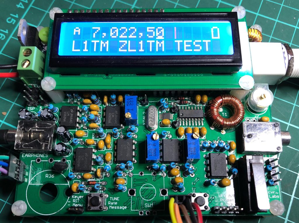
    My next mistake was to decide to test the radio using a  different voltage to earlier testing. I had read that the recommended range of voltage extends from 7 volts up to 16 (see page 5 of the manual), so I thought I’d use 9 volts. I think, also that the only way to reduce output power is by reducing the voltage. In any case, after I re-connected the radio, I noticed first of all that the sidetone was somehow delayed. If you sent a series of dits at say 15 wpm, you wouldn’t hear anything. And you had to hold the dash to hear it eventually.

    I had the dummy load connected to the antenna and tuned a local receiver with no antenna connected to the same frequency and noticed that actual signal was not delayed. That’s interesting! Is there component where the sidetone is generated introducing the delay? I also realised that I was actually getting some RF output which I measured at about 1.3 watts. The voltage was just over 9 volts and the RF voltage across the 50Ω dummy load was about 11 volts. The RF output was good but the delayed sidetone was a bit like talking with a delayed echo in your ears. Between this paragraph and the next, there was a fair amount of head-scratching and further checking.

    Then I decided I should see what the RF output is with a more regular voltage like 13.1 volts. I was delighted to see the voltage across the dummy load at 20 volts which neatly converts to 4 watts. And I was even more delighted to hear that the sidetone was back in sync with the key! So the lag appears to have been a result of the lower voltage. I’m not sure what the implications are of this if you want to wind back the wick and transmit at a lower output level. The signal sounded clean – it was just the sidetone that was laggy.

    Another thing I learnt during this phase of the troubleshooting was that a good way to remove the remnants of a component like a transistor is to melt some fresh solder on the joint to get the heat to flow more readily to loosen things up. I think I became better at using solder wick as well, with a dab of the flux pen. The printed circuit board stood up to my efforts replacing the transistor and other components like one of the toroid coils when checking the leads. I used a fine pointed iron tip at 370° C.

    Everyone says that the overwhelming majority of faults with home constructed electronics kits – at least 90% – are to do with the soldering not being up to scratch. So I figure all the time spent checking solder joints during assembly and afterwards paid off. If you tell yourself how much time you’ll save later, it becomes a more enjoyable part of the whole assembly process.

    I also finally managed to upgrade the firmware using the Arduino Uno and Avrdudess application. I had to force it but at long last, the application finally recognised the identity of the microcontroller in the radio. There must be a dodgy connection between the radio and the Arduino.

    Now I’m confident it’s working as it should I should make some contacts and then work my way through the manual again to confirm all is as it should be. But I will be much more careful checking any voltages!

    And then I might start on my 30m QCX.

  • QCX video resources

    There are a number – probably set to grow – of YouTube videos dedicated to the assembly of the QCX.

    The most impressive, not just for its length, is the feature film length video by Roberto IZ7VHF. It’s a beautifully filmed love letter to the radio as well as a video record of Roberto’s build. It was recorded in September.

    Hans Summers recorded a 20-minute video introducing the QCX in early October.

    Kevin KB9RLW has recorded a 42-minute long video on building the QCX.

  • QCX CW decoding

    One of the aspects I’ve been surprised and impressed with is the quality of the CW decoding while sending. While playing with the onboard microswitch as a morse key I felt I needed to emphasise the length of the dashes for the encoder to resolve my sending. So I was pleasantly surprised at how well the decoding worked with a straight key and a sideswiper. These keys didn’t seem to impose the same timing expectations as the microswitch – which is odd because I believe they are wired across each other.

    In any case, the decoder was able to present a pretty reliable rendition of what I had sent with both keys. Other systems I’m familiar with are only successful with keyer generated CW sent on a paddle. I’ve only seen sideswiper CW decoded by the Begali CW Machine which is a bit more expensive than the QCX but essentially built around a tiny AVR Butterfly.

    Decoding in receiving on the QCX sometimes seems to be jeopardised by noise and static, although some quite clear and strong signals occasionally would not be decoded. I need to experiment more to do it justice and check what impact the speed adjustment has because ultimately it all must be using the same microcontroller code to decode the morse, sending or receiving.

  • QCX enclosure

    One topic on the QRPLabs discussion group is the ideal enclosure for the little radio. The designer Hans G0UPL planned for all controls to be mounted on the small 10 x 8 cm PCB and provided for those who prefer to mount it in a protective enclosure.

    As mounted on the PCB the shafts of the AF gain control and the rotary encoder are slightly different lengths and the tiny momentary switches are a long way from any front panel.

    Part of the appeal of such a small radio is being able to show it off to friends so in one sense especially for this prospective audience an enclosure denies this pleasure – unless of course its transparent.

    For the moment at least I think I may stumbled on to a neat solution. On the kitchen bench.

    A suitably sized plastic container

    The price is right and it’s tasty too!

    Almost made to measure!

    This way I can keep tweaking the radio and store it with a degree of protection. I started out with this 40m version with the pot and encoder connected by headers with a view to finding an enclosure later, but this solution feels a little neater and safer. And there may even be space for a battery.

  • QCX CW transceiver

    I plan to use this category of my blog as a kind of sub-site to track the building of this delightful new transceiver kit from Hans Summers G0UPL and his QRP Labs. Since its launch in late August when all stock sold out in a day, sales of the QCX CW Transceiver continue at a pace that still surprises the developer as he prepares his fourth batch of 500 kits.

    This is my QCX in action receiving and decoding signals during the Oceania DX CW contest this past weekend

    It is a feature packed design focused on delivering an up to 5-watt single band CW transceiver. It includes built-in test equipment to be used during alignment and the QCX can be used as a WSPR beacon.

    It’s such a compact design – the PCB is 102 x 81mm with a hard working blue 16 x 2 backlit LCD display – and with its tiny onboard microswitch that can be used a key, it should probably be renamed the QTX!

    It boasts a long list of design features that seem amazing for the modest price of US$49. They include a Class E power amplifier, 7 element Low Pass Filter, CW envelope shaping free of key clicks, at least 50dB of unwanted sideband cancellation, a sharp 200Hz CW filter, Si5351A Synthesized VFO with rotary encoder tuning down to 1Hz, Iambic keyer or straight key option, CW decoder, displayed real-time on-screen, S-meter, Full or semi QSK operation, Frequency presets, VFO A/B Split operation, RIT, configurable CW Offset, Configurable sidetone frequency and volume and can be connected to a GPS interface for reference frequency calibration and time-keeping (for WSPR beacon)!

    Also super impressive is the quality of the 138-page long assembly instructions that make Heathkit style instructions seem abrupt! Nothing else comes close to the thoroughness of this document. As well as getting a radio that works, Hans clearly wants builders to understand how it works and why he chose the components he did. Prospective builders can download it freely from his site.

    Firmware for the ATmega328P microcontroller is up to version 1.00B and available from the QRP Labs groups.io group. It is not open source.