This is where I plan to work on the information available about the KGD Antenna. The centre coil form apparently used to be sold as a kit by QRP projects in Germany.
All this information is sourced from their site. (Here is their English translation of the main page – the pdf manual is not translated AFAIK).
To simplify the process – I hope – I’ve tried generating a rough first pass translation via Yahoo’s Babelfish site. I’ll work on that as time permits.
Just like any text translated into any language and then translated back again, these translations may be more hilarious than informative, but it’s a start…
The part following this English page re-write is sourced from the copy on the main web page. There is some overlap with the pdf file also translated later on this page. It’s a bit repetitive at the moment but the idea is to distill it all down to something practical and unambiguous.
——
lightly edited English translated page:
Lots of hams are not able to install a standard antenna. Some German QRPers designed the KGD – that’s a German nickname for a ‘very short dipole’, that can help these friends because it’s really small but very efficient.
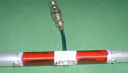
The 40 metre version of the KGD is only about 150cm long. The dipole is made from two 20mm diameter aluminium tubes and two 18mm diameter coils.
The middle of the KGD is made from polyamide. The coils are wound with 0.8 mm enamelled wire. To match the 50 ohm coax impedance, we use a capacitor rated at 6 kV.

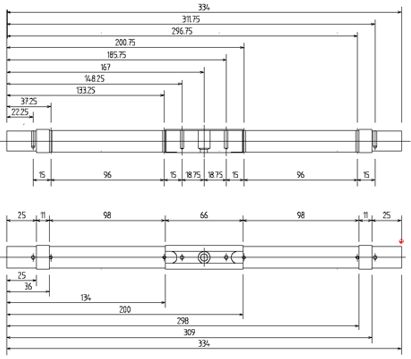
(This diagram shows the dimensions of the turned centre coli former. It’s intended to hold aluminium tubes of 18mm internal diameter – presumably so their outer edge lines up with the end of the coil space.)
There are short tuning rods at both ends of the KGD. Tuning is very reproducible. We tested ten KGD 40m antennnas and they all tuned up within +/- 5 kHz of the same frequency. Bandwith for VSWR 2 is about 45 kHz at 40m.
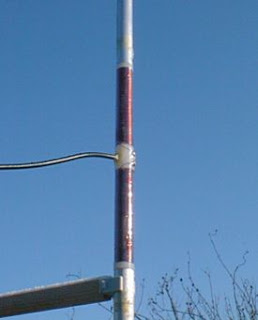
We used RG58 coax to feed the KGD. Our special mast to antenna holder is designed to enable horizontal or vertical mounting on a fishing pole. If the KGD is mounted vertically, the coax must be attached at a 90 degree angle for at least one metre.
The QRPproject KGD is limited for 100 Watt RF power maximum
We ship KGD kits from stock. The coils are pre-wound and the capacitor installed. You only need to add the tubes and the coax.
WARNING:
Take care that no one can touch the KGD during transmit. Even with five watts there are extremely high voltages at the dipole.
The KGD is not longer available.
——
KGD – Short ‘sawn-off’ dipole
Drawing on recently published material a small DL-QRp-AG working group developed an antenna for those with restrictions on what they can erect. We call this antenna
the KGD = (K) urz (G) eratener (D) ipol or Short ‘sawn-off’ dipole
The 40m band version of the KGD antenna is exactly 150 cm long (4ft 11in)and 2 cm (3/4in) diameter. The special feature of the KGD is that it is incredibly immune to the environment, and it performs well. Essentially it’s a system with two series resonant circuits and a tube (?) capacitor. With a transmit power of just 3 watts fed to the antenna, a voltage tester 10cm away glows like a Christmas tree. In practical testing there was barely an S-point difference with the G5RV on the other side of the house.
The KGD was originally launched in two forms: a simple homebrew version and a kit. This data here outlines the simple homebrew version and there used to be a kit available with the turned centre section made from Polyamide, with ready-wound coils and the pipes prepared and cut to length. So there used to be a choice to build the KGD completely or buy the kit. The kit is no longer available.

The coil form of the QRPproject version was made of Polyamide. The spaces on the left and right were supplied pre-wound with 0.8mm diameter (18 awg /21 swg) copper wire. A fixed capacitor was inserted to match the cable impedance to the feedpoint resistance of 20 ohms. The OMs tried to couple the 2:1 balun directly without a fixed capacitor, and likewise coupling with condenser and using a 1:1 balun was quite successful.
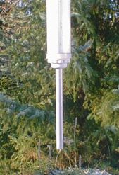
The centre section of the KGD can be made weatherproof by covering it with a heat shrink sleeve. If the KGD is to be installed outside permanently, we recommend enclosing the centre section in a plastic tube.
There are tuning rods at both ends of the dipole. They can be adjusted to balance out any possible environmental effects. On the most critical band – 40m – all the KGD antennas tested so far were able to be tuned in each band segment. The range between the points where SWR was 2:1 was about 45 kHz.
RG58 coax is used to feed the antenna. The mast support (KGD-MH) was arranged so that the dipole could be fastened horizontally or vertically to a mast or a fishing rod, or it could even be screwed to to a roof slat. When mounted vertically the coax cable must be led away from the dipole at 90 degrees for a metre or two.
The KGD from QRPproject can handle up to 100 Watts, but as staunch QRPers we consider this a waste of energy 🙂
—-
If the resonant frequency is below the respective band, then the antenna is tuned by unwinding a turns. NOTE: Always remove only one turn from each side at the same time and measure again.
| Pipe length for each side | Turns 0,8mm copper wire per side | |
| 80m (no kit!) | 160cm (20mm ID) | 258 turns close wound on 20mm core, adjustment with coupling coil |
| 40m | 70cm (18mm ID) | 114 turns close wound on 18.5 mm core adjustment also with tap with 1,5 Wdg or condenser 470pF |
| 30m | 50cm (18mm ID) | 71 turns close wound to 18.5 mm core adjustment with condenser 330pF |
| 20m | 35cm (18mm ID) | 47 turns close wound on 18.5 mm core adjustment with condenser 220pF |
| 17m | 30cm (18mm ID) | 35 turns close wound on 18.5 mm core adjustment with condenser 220pF |
Please note: production of the KGD has ceased. The only option available now is to build it yourself. Make sure the components and materials you use can handle the power you plan to apply.
——–
This is the copy appearing in the pdf at the ‘Baumappe’ link at http://www.qrpproject.de/Media/pdfual.pdf.
QRPproject
QRP and homebrew international
KGD
(K)urz (G)eratener (D)ipol
Thank you for choosing the KGD.
The KGD was developed by a small working group of the DL-QRP-AG after enthusiastic studies of the literature on shortened antennas.
Our goal was it to build as efficient an antenna as possible for those with few or no possibilities to erect an antenna. While the KGD can naturally be used portably, our prime concern however is with a stationary installation, whether on a balcony or in your allotment garden.
The efficiency of the KGD is enormous. Compared to a standard dipole at the same height as the KGD, large differences apparent. The directivity of the KGD is exactly like the standard dipole with the same figure of eight field strength. The side absorption must be considered when comparing the two antennas.
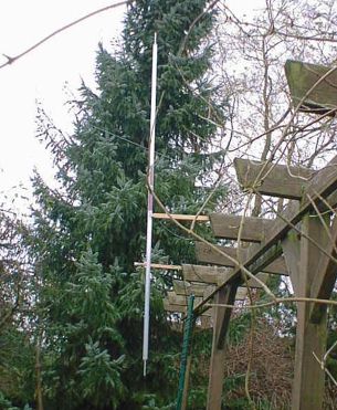
At ground level it is better to install the KGD vertically. That is because of the fact that horizontal waves at ground level are much more strongly absorbed. In practice with a height (of the bottom of the antenna?) about 2m above the ground we have noticed 2-3 S-points difference between horizontal and vertical installations.
With vertical installation the feed cable must be led away at least 1 meter at a 90 degree angle to the dipole.
During vertical installation two or four dipoles can be connected to a single feed cable, if there is at least 1 m distance between the dipoles.
An extension of the length of the antenna pipes worsens the total result. In the designed form of the KGD the relationship of length to diameter to inductance is optimised in such a way that the KGD only radiates the electrical field, differently to a shortened wire dipole. The antenna pipe contributes at the same time a top loading. The co-ordination tuning rods to the ends of the KGD enable adjustment of the overall capacity.
The feed point impedance of the KGD amounts to about 20 ohms. Adjustment to 50 ohms of a coax cable uses a capacitor of the appropriate computed value. The coax cable connects directly to the KGD without additional Balun. Users tests resulted in that one under certain circumstances further improvements can be achieved with a 1:1 Balun. The KGD without condenser might be able to be fed directly with a 2:1 Balun. These experiments are however yet to take place.
WARNING: All versions of the KGD generate extremely high voltages on the emitter tubes. It is absolutely imperative that during the transmit mode nobody is able to be close to the KGD. We must point out expressly that even with tests between 1 and 5 Watts there is a substantial danger of injury present!
Should you encounter problems anywhere or have suggestions for improvement, then contact Peter, DL2FI, who is pleased to help you at any time when able. You reach QRPeter best by email under the address: support@qrpproject.de or by telephone under ++49 (30) 85961323
Structure of the KGD
The coil for the QRPproject KGD is wound with the recommended number of turns for everyone. To start it is advisable to complete turns up to the target number.
All parts (provided in the kit that is no longer available) are properly matched, bored, turned or milled. It’s evident from the design, where solder taps are installed and the wire ends are temrinated at a carefully measured distance. The condenser provided is installed and soldered in such a way between the taps that it bridges the two dipole halves.
The final assembly involves a RG58 cable installed in the center section. Seal and coating are stripped the wire and soldered and bolted with the solder taps as is to be seen in the design. After soldering the borehole and the cable end should be sealed with acetic acid-free Silicone rubber, to make the fitting around the cable end water resistant. A coaxial connector of your own preference is connected to the other end of the cable. The length of the feed cable is arbitrary.
Next the antenna coil tubes are pushed onto the centre piece. The respective end of coil is screwed to the attached solder tap on the antenna tube. It’s important to use the provided screws. With unsuitable screw material the danger exists of corrosion through local cells. The provided aluminum tuning rods are pushed into the ends of the antenna tubes.

The KGD is now ready for a first test. If our fixing clip were also ordered, this is attached at the center piece and the KGD can be put on direct on a Spieth mast or a sturdy fishing rod. An antenna analyzer or the transmitter and one VSWR measuring instrument can be used to identify where the working frequency of the KGD. In our experience it would now already be near the AFU appropriate to the dimensions used. Adjust the two tuning stubs – evenly – to move the resonant frequency to the desired operating frequency.
The resonant frequency should be below the dimensions and adjustment must be done a turn on each side of the dipole. CAUTION, only adjust one turn on each arm at a time and then measure again.
For short-time duty in practice it appears that apart from the sealing of the feed cable no further isolation is advisable. Painting the wire or similar measures does shift the resonant frequency very strongly downward and does reduce the quality. It is better, with such a short term installation to work without applying further insulation.
If the KGD is to be installed permanently outside, then we recommend making it weatherproof by pushing a plastic pipe over the center section at least, which helps to insulate the dipole pipes.
Much success with the KGD and many QSOs
72/73 de DL2FI
© QRPproject Saarstr. 13 12161 Berlin http://www.QRPproject.de Tel: +49(30) 859 61 323 e-mail: support@QRPproject.de